22
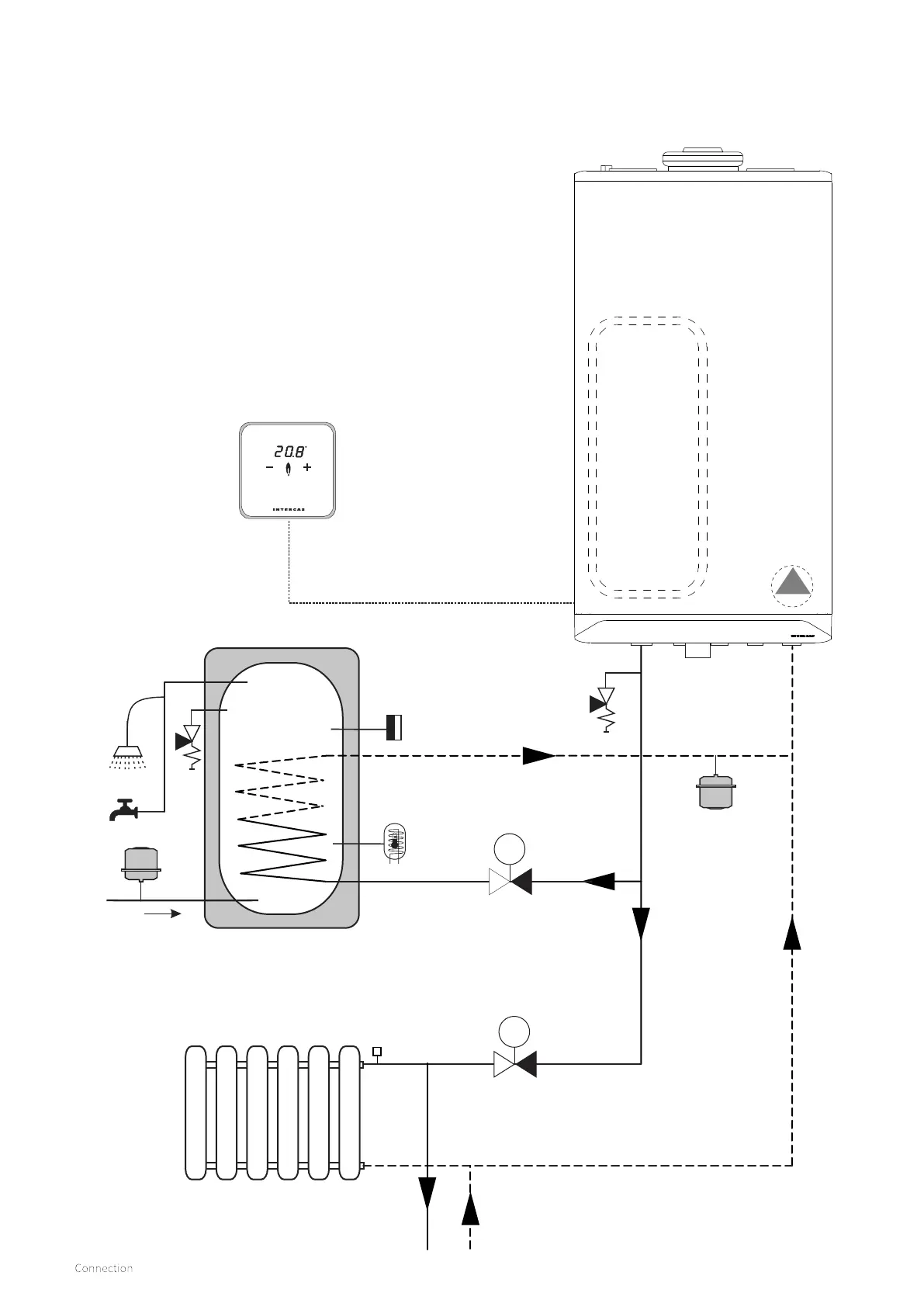
7.1.4 X-Plan zone Hydraulic diagram
A
B
C
D
E
Built in 6 ltr
expansion vessel
ErP modulating
pump
Key to Hydraulic & Wiring diagrams
A. Honeywell V4043H DHW Zone valve (Normally closed)
B. Honeywell V4043B Heating Zone valve (Normally open)
C. OpenTherm room thermostat (or programmable OT type if
not using the boiler intergral timer option for the heating
D. Cylinder overheat thermostat (manual reset)
E. Cylinder NTC sensor (art. no. 065117)
F. Pressure relief valve (3 Bar)
G. T/P safety (8 Bar)
H. Expansion vessel (potable)
m
m
Additional expansion
vessel option see §7.1.1
Stainless steel unvented cylinder (≥30 kW coil)
(storage capacity to be established by the installer)