EasyManua.ls Logo

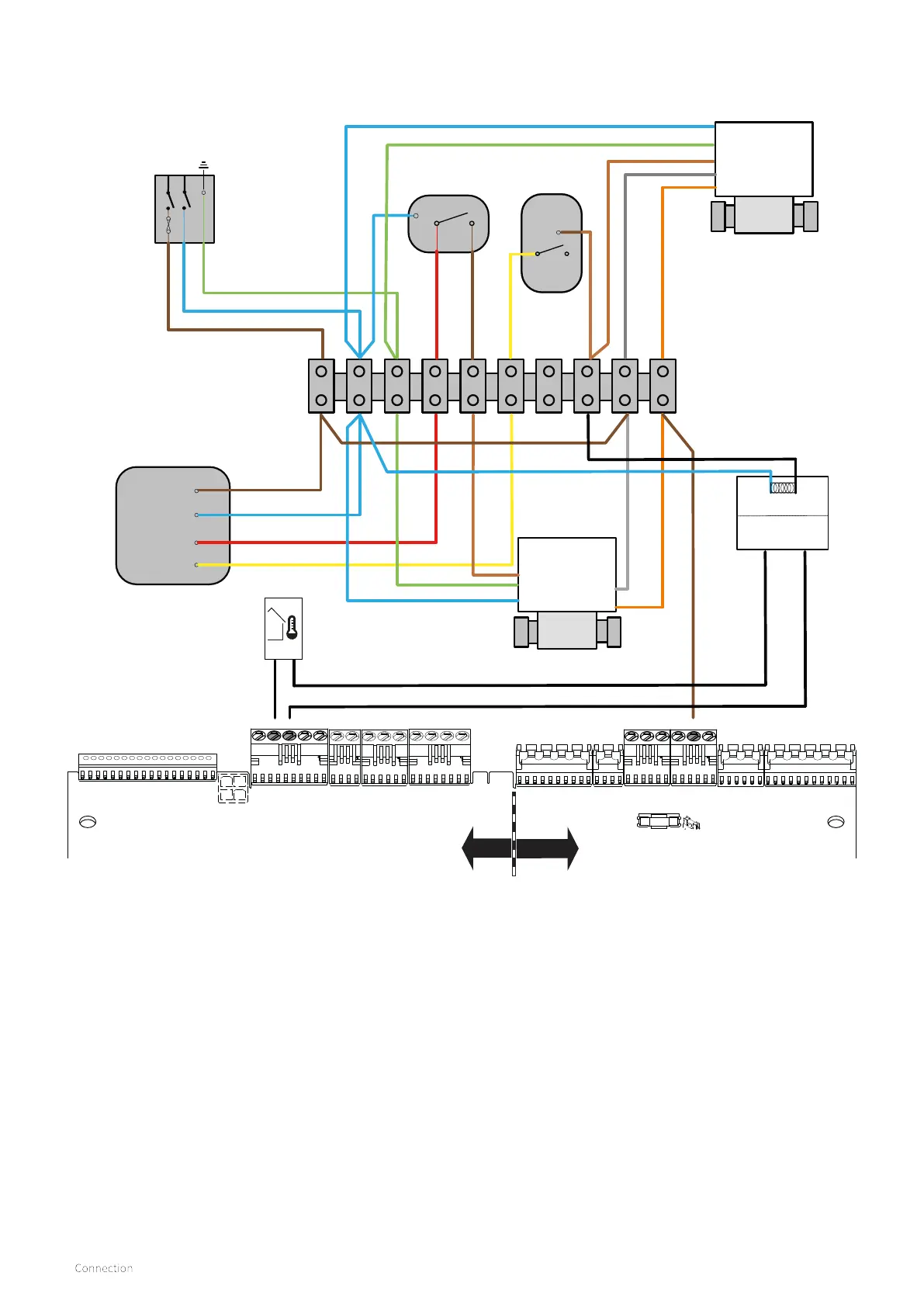
Intergas Xclusive 30 - S-Plan Wiring Diagram (with Outside Weather Compensation Kit)

Intergas Xclusive 30
92 pages
Print Icon
To Next Page IconTo Next Page
To Previous Page IconTo Previous Page
Loading...
26
X15
(24V=)
X14
X13
(24V =)
X12
(24V =)
X11
(24V =)
N/A
X10
(24V =)
N/A
X8
(230V ~)
X5
(230V ~)
X4
(230V ~)
X3
(230V ~)
X2
(230V ~)
X1
(230V ~)
F1 (3,15 AT)
FUSE
23 1234
34
5 1
24V=
230V
Zone Valve
D H W
V4043H
Room
thermostat
230Vac 3amp
Switched
Fused Spur
Wiring Centre
Zone Valve
C/HEATING
V4043H
Twin channel
Programmer
L
N
HTG on
EARTH
S/LIVE (DHW)
S/LIVE (HTG)
P/LIVE
P/LIVE
M/V S/L
NEUTRAL
G/YELLOW
L N
Cylinder
thermostat
BLUE
M/V S/L
DHW on
2
1
3
1
C
1 2
3 4 5 6 7 8 9 10
DHW S/L
HTG S/L
Outdoor Sensor S6
Relay Coil
N/C COM
50051W
7.1.8 S-Plan wiring diagram (With outside weather compensation kit)
LIVE SUPPLY
S/LIVE (BOILER)
Note:-
With all wiring diagrams when using a digital type room thermostat the Neutral wire from the
wiring centre (2) to room thermostat (2) will not be required.

Table of Contents