P/N 466-2478 (ML) • REV B • ISS 09JUL13 3 / 44
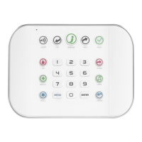
Area LED indications
See figure 1.
When the RAS cover is open or removed, 16 red LEDs are
visible at the bottom of the RAS. Each LED represents an
area, and the indications are as follows:
• The LED illuminates when its corresponding area is
armed.
• The LED flashes slowly when a fault is detected or when
an alarm occurs, in disarmed state.
• The LED flashes quickly when a fault is detected or when
an alarm occurs, in armed state.
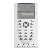
Operating features
Keyboard backlight and night light
The default keyboard backlight and night light settings are as
follows:
• Keyboard backlight on (bright) for approximately 4¼
minutes following a key press.
• Night light on (dim).
These functions can be changed from the RAS menu.
LCD contrast
The LCD contrast may be adjusted by pressing and holding the
Menu key while momentarily pressing the Up or Down arrow
keys to change the display contrast. The default setting is 12.
LCD backlight
The LCD backlight illuminates for 30 seconds following a key
press.
Buzzer tone
The Buzzer tone may be adjusted by pressing and holding the
Clear key while momentarily pressing the Up or Down arrow
keys to change the buzzer tone. The default setting is 16.
System fault buzzer
In case a System Fault occurs (no more communication to
control panel) the text “System Fault” appears on the display
and the buzzer will be activated until any key is pressed. The
setting “Auto” is used to enable this feature for countries where
this is a requirement. The setting can also be set to “On” or
“Off”. The setting can be changed by holding the Menu key
while momentarily pressing the 0 key. Each next press of the 0
key selects either “Auto”, “On” or “Off”.
Power up
Upon initial power up, the buzzer will sound two beeps
indicating that the internal non-volatile memory is OK. All of the
area LEDs may illuminate, indicating that the system is armed.
All areas must be disarmed in order to enable access to the
installer programming menu options.
Troubleshooting
General faults
No LED or LCD display:
• Verify the +13.8 and 0 V wire connections on both the
RAS and the power supply.
• Verify power output on the DGP or external power supply.
Area and Status LEDs are flashing and the LCD display reads
System Fault:
• Verify the D+ and D− wire connections (may be reversed
or open circuit).
• Verify the address DIP switches of the RAS is set to the
proper address.
• Verify that the control panel or four-door DGP is polling the
RAS address.
ATS1115A RAS with Smart Card reader does not respond to
a Smart Card:
• The RAS may actually be an ATS1110A type that is not
fitted with a Smart Card reader.
• The Smart Card may not be programmed (blank).
RX and TX LED Indications
RX and TX LEDs are provided on the circuit board to assist in
fault diagnosis, and are visible when the rear plastic cover is
removed.
• Rx: The yellow Rx LED flashes to indicate polling data is
being received on the system bus from the panel. If the
LED does not flash, the control panel is not operational or
the bus is faulty (usually cabling).
• Tx: The red Tx LED flashes to indicate the RAS is replying
to polling from the control panel. If the Rx LED flashes but
the Tx LED does not, the RAS is not programmed to be
polled in the control panel or is addressed incorrectly.
Programming map
UTC F&S, RAS1110.V05
0-EXIT, Menu:
1-Access LED options
0-EXIT, Menu:
LED enabled
*-Change, #-Exit
2-Night Light Options
0-Exit, Menu:
Night Light On
*-Change, #-Exit
3-Keypad Backlight Options
0-Exit, Menu:
Keypad Backlight On
*-Change, #-Exit
4-RTE (Egress) Control
0-Exit, Menu:
RTE Only
*-Change, #-Exit
 Loading...