Do you have a question about the Interlogix ATS7320 and is the answer not in the manual?
Enables alarm reporting via GSM for various ATS panel series.
Details on ATS7320-SIM module, UltraSync SIM card, and service costs.
Requirements for GSM card subscription and antenna placement.
Specifies that the ATS7320 must be mounted inside an ATS panel housing.
Step-by-step guide for mounting ATS7320 into specific ATS control panels.
Steps for mounting ATS7320 into ATS1000, ATS4000, and ATSx000A-MM panels.
Procedure for connecting the ATS7320 GSM module to the control panel.
References for operating instructions and programmable functions.
Guidance on testing the GSM module's correct reporting to the Central Station.
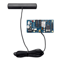
Details on the ATS7320 module components, including connectors and LEDs.
Explanation of the DIP switch functions for the ATS7320 module.
Indicates the status of the communication interface to the panel.
Indicates the status of the power supply for the GSM module.
Indicates the status of the GPRS communication.
Indicates the status of audio information transmitted to the central station.
Indicates the field strength or signal strength found by the GSM module.
Indicates the status of the network connection for the GSM module.
Indicates the status of the SIM card inserted into the module.
| Brand | Interlogix |
|---|---|
| Model | ATS7320 |
| Category | GSM/GPRS Modules |
| Language | English |