P/N 146550999-1 • REV C • ISS 30APR12 5 / 36
For a single zone with all onboard resistors set, the zone
resistance can be the following.
Table 2: Zone resistance values
Zone state Value Default
Tamper (short) 0 Ω 0 Ω
Normal Rt 4.7 kΩ
Alarm Rt+Ra 9.4 kΩ
Tamper (open) ∞ ∞
DIP switches
Table 3: SW1, general settings
Switch Values
6: LED On: LED on* Off: LED off
5: Remote On: Remote on Off: Remote off*
4: Reserved
3: Polarity On: Positive polarity Off: Negative polarity*
1, 2: Radar
range
1 On, 2 On: 12 m (39 ft.)*
1 Off, 2 On: 9 m (30 ft.)
1 On, 2 Off: 6 m (20 ft.)
1 Off, 2 Off: 4 m (13 ft.)
* Factory default
DIP switch SW1
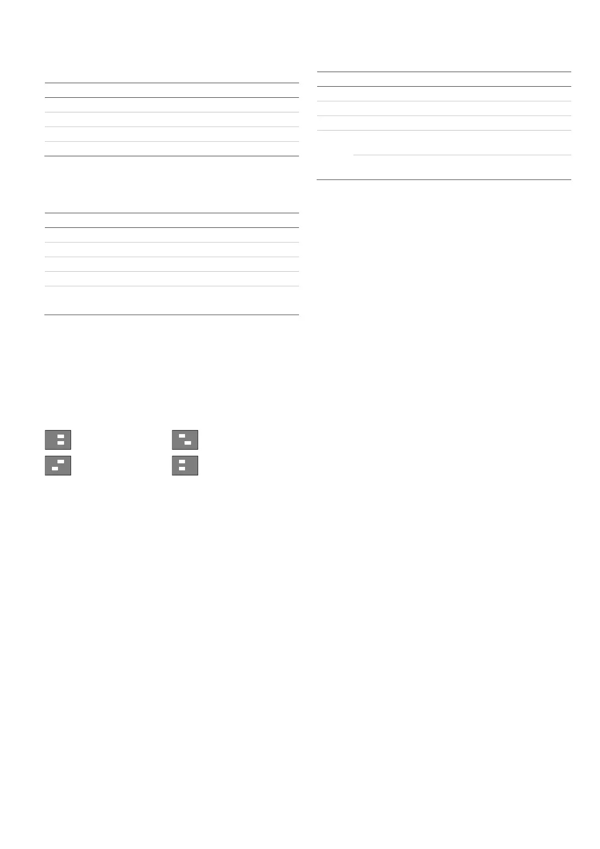
SW1-1, SW1-2: Radar range
Use SW1-1 and SW1-2 to set the radar range exactly to fit the
application. The radar is of a range-gating type which means
that the range of detection is very accurate.
ON
12
4 m (13 ft.)
ON
12
9 m (30 ft.)
ON
12
6 m (20 ft.)
ON
12
12 m (40 ft.)
Factory default.
SW1-3: Polarity
On: Positive polarity. Configures the inputs (WT and D/N) as
“Active high”.
Off: Negative polarity. Configures the inputs (WT and D/N) as
“Active low”. Factory default.
The functionality is explained in Figure 9.
Figure 9 legend
(1) Polarity high
(2) Polarity low
(3) Walk test
(4) Day/night
This function also depends on the SW1-5 setting. See “SW1-5:
Remote functionality” below.
SW
1-4: Reserved
Do not change.
SW1-5: Remote functionality
On: Remote on. Enables WT and day/night inputs.
Off: Remote off. Disables WT and day/night inputs (factory
default).
The following functionality depends on the Remote setting.
Table 4: Functions dependent on the Remote setting
Item Description SW1-5 Remote on SW1-5 Remote off
SW1-3 Polarity Selectable Positive only
WT WT input Enabled Disabled
D/N D/N input Enabled Disabled
Other Green Mode Enabled in day
mode with no WT
Disabled
Alarm memory Enabled in day
mode with no WT
Disabled
See also “Connections” on page 4.
SW1-6: LEDs
On: LEDs are enabled. See “LEDs and outputs” on page 6 for
LED functio
nality.
Off: LEDs are disabled for any state.
Configuring the coverage pattern
• Remove blinders (Figure 8, item 1) if necessary. The
modified pattern is shown in Figure 8, items 3 to 7.
Note: If both blinders are installed, the detector range is
limited to 6 m (default).
• Modify the pattern by breaking out blinder parts (shown as
gray in Figure 8, item 1). The corresponding curtain
fragments are shown in Figure 8, item 2.
• Put the appropriate mirror stickers if necessary. See
Figure 7, item 1 for details.
Caution: Removing stickers can damage the mirror
surface.
• When near objects directly under the detector, fit the mask
to the inside of the window (default). This disables the part
of the curtains looking down at the object, whose
closeness might destabilize the detector. See Figure 7,
item 2.
Walk testing the detector
There are two ways for switching on the walk test mode.
SW1-6 set to LED on, SW1-5 set to Remote off
In this mode the LED indication is always enabled (constant
walk test mode).
SW1-6 set to LED on, SW1-5 set to Remote on
This setting enables the walk test input (pin 7) and the
day/night input (pin 8). This allows the user to activate LED
indication remotely by setting the detector into the day mode
and activate the walk test.
Green mode
When SW1-5 is set to Remote on, the radar is switched off
during the day mode (with no WT) to reduce current
consumption. The detector is then operating in PIR only mode.
Note: The Day/night line must be connected to the control
panel for this mode to work.