4 / 16 P/N 144553999-3 • REV C • ISS 01MAR19
EN: Installation Sheet
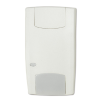
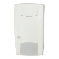
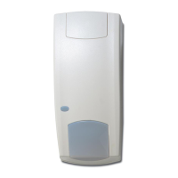
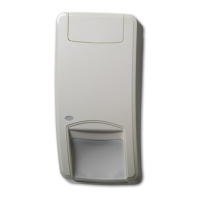
Siting the detector
See figure 4.
Install the detector so that the expected movement of an
intruder will be across the fields of view. This is the direction
best detected by PIR detectors.
Avoid possible false alarm sources such as:
• Direct sunlight onto the detector
• Heat sources in a field of view (heaters, radiators, etc.)
• Strong air draughts onto the detector (fans, air-
conditioning etc.)
• Large animals (dogs, cats) in a field of view
• Obscuring the detector field of view with large objects,
such as furniture
We recommend that the detector is regularly walk tested and
checked back at the control panel.
Mounting instructions
1. Lift off the insert (item 1) as shown in item A or B. Apply
pressure (C) on insert during sliding (D) or turning (E).
2. Open the detector (items 2 and 3).
3. Break out one or both cable entry holes (item 4) as
required.
4. The detector should be mounted at a height of 1.8 to
3.0 m.
5. Select mounting holes for corner (item 8) or flat wall
(item 9) mounting.
6. Use the base as a template for marking screw hole
locations on the wall.
7. Fasten the base to the wall.
8. Strip cable for 5 cm and pull it through the cable entry
holes (item 4) and strain relief (item 7).
9. Wire detector as shown in Figure 5.
It is easier to wire by taking out the connection terminal
(item 11).
Use the optional spare terminal (item 6) if necessary.
Mounting hole for swivel bracket SB01: item 10.
10. Place the cover (item 2) in the base (item 3), insert the
screw (item 5), and place the insert (item 1).
Area coverage
The area coverage is shown in Figure 9 (EV100 and EV100PI)
and Figure 10 (EV105).
Note: Item 1 shows a general installation area coverage,
item 2 is the area coverage for EN 50131 compatible
installations.
LED function and remote control of LED
To walk test the detector make sure the wire jumper (from
terminal 1 to 7) is on the connector, or terminal 7 is remotely
connected to system ground. See Figure 5.
Programming the sensitivity (process
mode)
Sensitivity is programmed according to the position of
jumper J1 (see Figure 6).
STD: Standard sensitivity. Suitable for most wide-angle
applications and for single curtain pattern.
Bi-C: Bi-curtain mode. In this setting an extra level of
processing is applied to provide enhanced stability in the
presence of false alarm hazards in smaller areas. Not suitable
for single curtain applications or a range less than 1.5 m
(Figures 9 and 10) and at high risks.
Note: Bi-Curtain is used to reduce the possibility of false
alarms. It looks for signal verification and requires the intruder
to be seen in two curtains for an alarm. Not to be used in
undercrawl and long range application.
Programming the range
Program the range at jumper J2 (see Figure 6).
For range under 6 or 10 m for EV100(PI), and 7 or 12 m for
EV105.
It is important to program the sensor correctly for optimum
sensitivity.
Note: Range reduction will reduce PIR-sensitivity in the
undercrawl area.
STD = Standard.
Bi-C = Bi-Curtain
Always select the appropriate range setting for the dimensions
of the protected area.
Verify coverage pattern and adjust if required.
When jumper J1 or J2 are not used in a “bridge” situation, the
jumpers must be mounted in the upper position.
If not, they cause a problem by closing the detector (see
Figure 6).
EV100(PI) only (PI = PET Immunity)
This detector is designed to be immune up to certain size of
pets.
Pets up to 20 Kg normally will not cause any problems in
standard applications.
Advised minimum mounting height in PI-application: 2.4 m.
Larger pets can be allowed for by alternative mounting PI-
detector upside down at 90 cm from floor. See Figure 7.