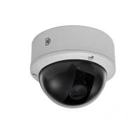
EN - 6 UVD-IP-XP4DNR(-P) Camera
Connecting analog cables
To connect the cables:
1. Connect a coaxial cable from the camera’s BNC connector to a
CCTV monitor or video recording device.
2. Connect a PoE switch, a 12 VDC or 24 VAC power supply to the
power input. Do not connect both the PoE connection and DC or
AC connection at the same time. The label on the camera gives
the following information:
Red cable. Power in.
Black cable. Power in.
White cable. Video out.
Black cable. Video ground.
Note: For 24 VAC or 12 VDC, Black or Red may be used for ground.
Installing the camera
To mount the camera, attach the camera to the mounting surface using
the appropriate fasteners.
Angle adjustment
To adjust the horizontal angle of the platform up to 180 degrees, turn
the platform (Figure 4 on page 7).
To adjust the horizontal angle of the rotor up to 350 degrees, turn the
rotor on the platform (Figure 4 on page 7).
To adjust the vertical angle of the platform up to 90 degrees, turn the
platform (Figure 4 on page 7).
 Loading...
