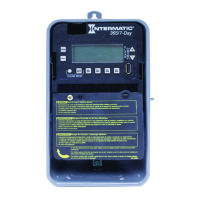
Electronic 7-Day
Time Switch
Installation and User Instructions
MODEL ET1700 Series
With Battery
Carryover
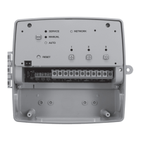
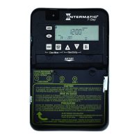
Front View
Rear View
B
A
Time Switch
• Input Voltage: 120/208/240/277 VAC, 60 Hz
• Power Consumption: 6.0 W Max.
• Contact Conguration: SPST (ET1705C), DPST (ET1725C), and
SPDT (ET1715C). See wiring diagrams on next page.
Switch Ratings—ET1705C, ET1725C (per pole)
• 30 A Inductive/Resistive, 120/240 VAC, 60 Hz
• 20 A Ballast, 120-277 VAC, 60 Hz
• 20 A Resistive, 28 VDC
• 5 A Tungsten: 120/240 VAC, 60 Hz
• 1 HP, 120 VAC, 60 Hz
• 2 HP, 240 VAC, 60 Hz
Switch Ratings—ET1715C (NO/NC) Normally Open/Normally Closed Contact
• 20 A/10 A Inductive/Resistive, 120/240 VAC, 60 Hz
• 20 A/3 A Ballast, 120-277 VAC, 60 Hz
• 5 A Tungsten: 120/240 VAC, 60 Hz
• 1 HP / ¼ HP, 120 VAC, 60 Hz
• 2 HP / ½ HP, 240 VAC, 60 Hz
Set Points (Events)—Each load output of the Time Switch can support
up to 14 timed ON and 14 timed OFF events per day.
Battery-Powered Clock Operation—3 years minimum (uses 2 AAA indus-
trial grade alkaline batteries, supplied)
Minimum ON or OFF time—1 minute
Maximum ON or OFF time—6 days, 23 hours, 59 minutes
Shipping Weight—2.5 lb. (1.1 kg)
The Intermatic ET1700 Series Electronic 7-Day Time Switch
automatically switches loads to a preset weekly schedule with to-the-
minute accuracy.
The independent 7-day programming provides complete exibility for
applications where load switching differs each day of the week.
Use the ET1700 series as an ON/OFF timer in applications requiring
7-day load control such as lighting, air conditioning systems, pumps,
etc. Each load output of the Time Switch can support up to 14 timed
ON and 14 timed OFF events per day. The program can be overridden
by pushing the ON/OFF load override button(s).
The ET1700 Series Time Switch is designed to directly switch tungsten
or ballast loads up to its rating, and inductive or resistive loads up to
30A at 120, 208, 240, or 277 VAC.
Specifications
Description
WARNING
Risk of Fire or Electric Shock
• Disconnect power at the circuit breaker(s) or disconnect switch(es) before installing or servicing.
• Installation and/or wiring must be in accordance with national and local electrical code
requirements.
•
For outdoor locations or wet locations (rain-tight), conduit hubs that comply with requirements of
the UL514B (standard for fitting conduit and outlet boxes) are to be used.
• This enclosure does not provide grounding between conduit connections. When metallic conduit
is used, you must also install grounding type bushings and jumper wire.
• For plastic enclosures, bonding between conduit connections is not automatic and must be
provided as part of the installation.
• Use #18 - #10 AWG wires, rated at least 75°C - COPPER conductors ONLY.
• If the power disconnect point is out of sight, lock it in the OFF position and tag it to prevent
unexpected application power.
• Make sure there is no wire insulation under the terminal plate on the time switch connector.
Firmly tighten terminal screws.
• Do not remove insulator that is covering terminals.
• KEEP DOOR CLOSED AT ALL TIMES when not servicing.
NOTICE
• Do NOT touch circuit board components, contact can create a static discharge, which can
damage the microprocessor.
Enclosures—Three enclosure options are available.
• ET17x5C – TYPE 1 indoor metal enclosure
• ET17x5CR – TYPE 3R indoor/outdoor lockable metal enclosure
• ET17x5CPD82 – TYPE 3R indoor/outdoor lockable impact resistant
polycarbonate enclosure with clear cover
Knockouts—Combination 1/2-3/4 inch size, 1 on back and each side,
2 on bottom
Wire Size—AWG #18 through #10
Slide down
to remove
battery case
Tilt top forward
Installation Instructions
3. The timer is shipped with DST (Daylight Saving
Time) enabled. To disable DST, insert a jumper
at location marked DST. See location B in Rear
View above and detail at the right.
4. ET1725C ONLY—Decide whether you want
to control multiple loads simultaneously (SIM),
independently (IND), or with a 2-second pulse
(PUL) (e.g., for use with mechanically held
contactors or bell ringing applications), and
make sure the jumper is positioned accordingly.
See location B in Rear View above and detail
at the right. (The unit is shipped with the loads
set for IND.)
2. Set voltage selector for desired input voltage.
The timer is shipped with voltage set for 120
VAC. To operate at 208, 240 or 277 VAC, move
the selector switch to the desired setting as
marked on the circuit board. See location A in
Rear View above and detail at the right.
1. Remove the mechanism
from the case by
depressing the catch at
the top of the case and
pulling out, as shown.