EasyManua.ls Logo

Intermatic ET8415CR - Wiring Diagrams; 4 x SPST Configuration; 2 x DPST Configuration; 2 x Pulse Configuration

Intermatic ET8415CR
4 pages
Print Icon
To Next Page IconTo Next Page
To Previous Page IconTo Previous Page
Loading...
XXXXXXXX
Energy Controls
ET8415CR
Diagrams
AC IN
COM1
COM2
COM3
COM4
NO-1
NO-2
NO-3
NO-4
Load 1
Load 2
Load 3
Load 4
L1
120
/208/240/277 VAC
Input
EXAMPLE:
4
x SPST
Operation Mode set to
IND
,
Input and Output voltage are the same
NOTE: Each relay is a
dry contact
.
Other voltages can
be used if dedicated
supply voltage is
used for COM
terminal replacing
L
1.
AC IN
COM1
COM2
COM3
COM4
NO-1
NO-2
NO-3
NO-4
Load 1
Load 2
L1
L2
EXAMPLE:
2
x DPST
Operation Mode set to
SIM
for both sets of contacts
,
Input and Output voltage
are the same
L3
L4
240 VAC Load
240 VAC Load
240 VAC
240 VAC
NOTE: Each relay is a
dry contact
.
Other voltages can
be used if dedicated
supply voltage is
used for COM
terminals
.
AC IN
COM1
COM2
COM3
COM4
NO-1
NO-2
NO-3
NO-4
Bell
Load 3
L1
120
/208/240/277
VAC Input
Neutral/L2
EXAMPLE:
2
x Pulse
Operation Mode set to
PUL
For both sets of contacts
,
Each ON and OFF event
for Circuit
1
will ring the bell
.
Each ON event for Circuit
3
will Close Contactor
and Each OFF event will Open Contactor
.
Closed
Open
COM
Maintained Contactor
Neutral/L4
L3
120
/208/240/277 VAC
28
VDC Input
NOTE: Each relay is a
dry contact
.
Other voltages can
be used if dedicated
supply voltage is
used for COM
terminals
.
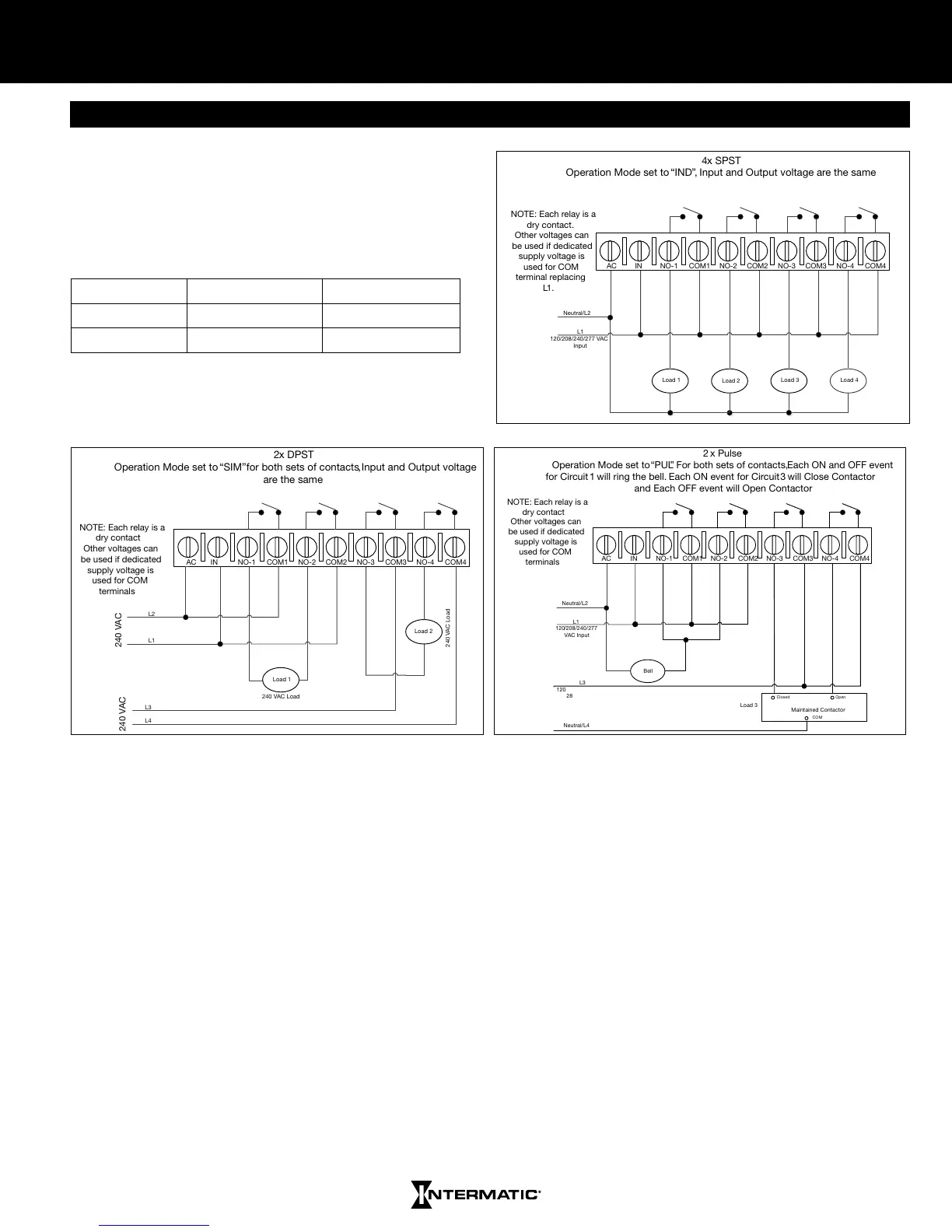
There are many different ways to set the relays on the
ET8415CR Time Switch. The four relays can be used
individually or in pairs of two. Refer to the table below for a
complete list of ways to set the relays and the illustrations
for some of the common wiring installations
IND/IND SIM/IND PUL/IND
IND/SIM SIM/SIM PUL/SIM
IND/PUL SIM/PUL PUL/PUL
Note:
IND= Independent SIM= Simultaneous PUL= Pulse

Related product manuals