29
User Manual
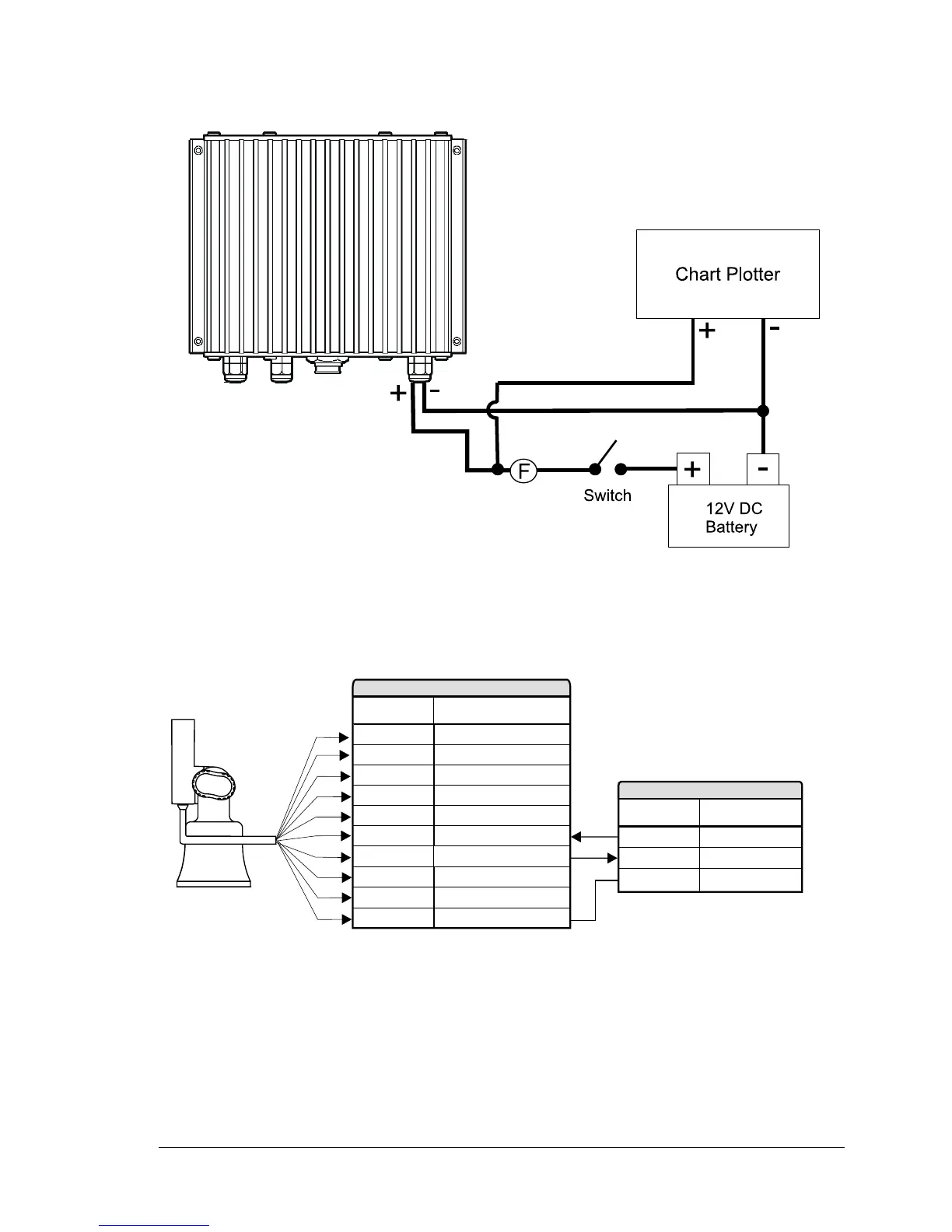
In the example below you will notice the positive DC power connection is run
through a switch and a fuse before connecting it to the 50-200 FISH FINDER and
the chart plotter.
Fig.4.6 - The 50-200 FISH FINDER Power Connection
4.7 CHART PLOTTER CONNECTION DIAGRAM
If the chart plotter has a quick disconnect bracket (see the chart plotter User
Manual) see the following picture to make the connection to the chart plotter:
GND/COMMON
+10-35 Vdc
RED
BLACK
OUTPUT1+
INPUT2+
OUTPUT2+
INPUT1+
INPUT1-
WHITE
GREEN
YELLOW
GRAY
BROWN
WIRE
COLOR
FUNCTION
INPUT3+
OUTPUT3+
SIGNAL GND
ORANGE
BLU
PINK
QUICK DISCONNECT BRACKET CABLE
BBFF TX+
GRAY
BROWN
WIRE
COLOR
FUNCTION
BBFF GND
BLACK
BBFF PLOTTER CABLE
BBFF RX+
Fig.4.7 - Connection to the Fish Finder for chart plotter with quick disconnect bracket
If the chart plotter has a 8 pin Power & I/O connector see the following picture: