8
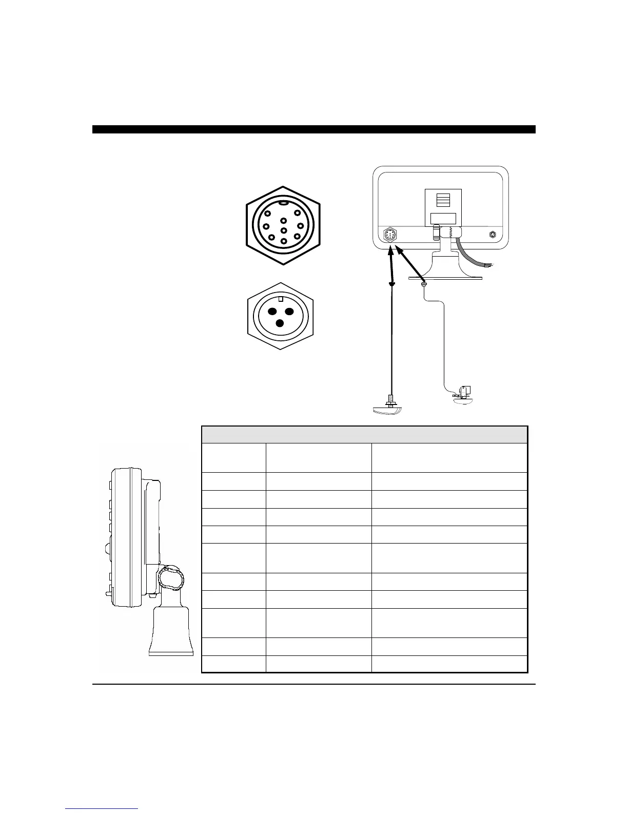
Wiring and Cable Connectors
9 Pin Transducer Connectors:
(view from front of female plug)
1 White 1st element
2 Brown 2nd element
3 Orange 3rd element
4 Yellow 4th element
5 Green 5th element
6 Blue 6th element
7 Violet 7th element
8 Gray 8th element
9 Shield Ground/Return
3 Pin Video Input
1 Ground Return
2 +12 VDC
3 Video Signal
Transducer Connector
Green = Vertical Scanning input
Main Power-I/O Wiring .
(Cable from Quick Disconnect Bracket)
WIRE
COLOR
DESCRIPTION FUNCTION
BLACK
GND/COMMON POWER SUPPLY GND (-)
RED
POWER +11-16 VDC POWER SUPPLY (+)
WHITE
RXA (+) GPS INPUT PORT
GREEN
RX-TX - GND - SERIAL PORT(s) RETURN
YELLOW
TXA (+) NMEA OUT/ MASTER-REMOTE/
SOFTWARE DOWNLOADS
BROWN
RXC (+) NMEA TEMP INPUT PORT
GRAY
+12 Vdc - OUTPUT 12VDC - FOR ALARM
ORANGE
RXB (+) MASTER-REMOTE/SOFTWARE
DOWNLOADS
PINK
TXB (+) N/C
BLUE
TXC - OUTPUT 3+ EXTERNAL ALARM SIGNAL
QUICK DISCONNECT BRACKET CABLE
Transducer Connections
1
2
3
TRANSOM MOUNT
THRU-HULL
(T1-I200-026)
(T1-I200-025)
Thru-Hull or
Transom Mount
Transducer