Page 14 of 80
TABLE 1 THERMOSTAT WIRE INFORMATION
WIRE SIZE MAX. WIRE LENGTH
AWG mm ft. m
22 0.6 10 3.0
20 0.8 25 7.6
18 1.0 40 12.2
16 1.3 64 19.5
14 1.6 100 30.5
2) After the unit is installed and the gas line hooked up, crimp a fork connector to each wire and
attach them to the TH/TP and TH screws located on the valve.
3) Check tests can be performed on the valve by using the trouble-shooting guide, Section 5.0.
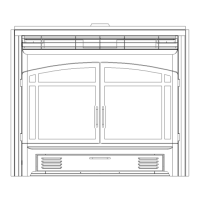
4) This switch may be connected in parallel with a thermostat, digital on/off remote or wall switch
(see Figure 4).
Figure 4
 Loading...