Do you have a question about the Intex Pure Spa BUBBLE SB-HWF20 and is the answer not in the manual?
Always unplug the power cord before replacing spare parts for safety.
Highlights QR code and red Wi-Fi chip on new Wi-Fi spa PCBs.
Lists necessary tools for effective spa control base repair procedures.
Guide on using a multimeter to measure AC and DC voltage correctly.
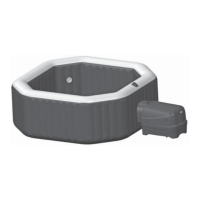
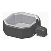
Overview of the control base, control panel, and spa tub components.
Troubleshooting steps for control panel failing to pair with Wi-Fi router.
Procedure for fixing transmission signal failure (Error E81).
Steps to troubleshoot network issues causing the spa to be offline.
Visual representation of the control base unit's electrical wiring connections.
Information related to the main circuit board within the control base.
Steps for safely opening the control base and removing panels.
Guide on removing the PCB cover and disconnecting wires.
Locating and identifying the Transformer (A) and Air Blower (B).
Identifying the PCB (C), Base (D), and Temperature Sensors (E, H, I).
Locating and identifying the Heating Element (F) and Flow Sensor (G).
Identifying water inlet/outlet parts (J, K) and air inlet nut (L).
Identifying the Electrical Cord with RCD (M) and Water Pump (N).
Mapping sensor types to terminal colors (Black, White, Green, Yellow).
Identifying terminals for power supply, transformer, blower, and heater.
Details on terminals for filter pump power, rectifier input/output.
Identifying terminals G & H for the hard water coil.
Troubleshooting steps for Error Code E81 related to signal transmission.
Steps to check RCD, reset, and replace panel if E81 persists.
Replacing the main circuit board or switch controller board for E81.
Code E90 indicates low water pressure due to obstructions or internal faults.
Diagnostic flowchart for resolving Error Code E90.
Checking flow sensor connections and simulating its function.
Procedure for replacing a defective flow sensor.
Troubleshooting a water pump that only clicks when turned on.
Steps to access and inspect the water pump's impeller and shaft.
Using a multimeter to test transformer voltage output.
Detailed steps for removing and replacing the transformer.
Checking the voltage at PCB terminals (A&B) for proper operation.
Instructions for replacing the PCB if it fails voltage tests.
Procedure for disconnecting and replacing the heating element.
Code E94 indicates very low water temperature, possibly from frigid water or sensors.
Diagnostic flowchart for resolving Error Code E94.
Steps to swap out and replace the 20-40°C water temperature sensor.
Replacing the PCB if E94 persists after sensor replacement.
Code E95 indicates very high water temperature, possibly from sensor issues.
Steps to add cold water or replace the 50°C sensor or PCB.
Code E97 indicates dry-fire protection, due to hot water or a faulty 84°C fuse.
Procedure for testing and replacing the 84°C thermal fuse.
Replacing the PCB if E97 persists after fuse replacement.
These codes indicate a faulty 20-40°C water temperature sensor.
Steps to replace the sensor or the PCB.
System hibernates after 72 hours of continuous heating, indicating heater or PCB issues.
Procedures for replacing the heater set or the PCB.
Blank panel indicates RCD, PCB, or connection issues.
Steps for resetting RCD and replacing the control panel.
Options include replacing PCB, RCD, or power cord.
Random display suggests a malfunction with the panel or PCB.
Guidance on replacing the control panel or the PCB.
Steps for diagnosing an air blower that fails to turn on.
Verifying terminal connections and checking air blower voltage.
Replacing the air blower or the PCB based on diagnostic results.
Using a psophometer to measure and assess air blower noise levels.
Investigating issues like bad check valves or pump lifespan for noise.
Procedure for testing and replacing the RCD unit.
Replacing the control panel and verifying voltage output.
Ensuring correct installation of waterproof rings on connectors.
Steps to access the PCB by removing the cover and disconnecting wires.
Procedure for installing the replacement main circuit board.
Steps to remove the old base and install a new one.
Instructions for removing the switch controller board.
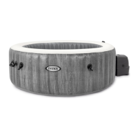
| Material | Fiber-Tech construction |
|---|---|
| Model | SB-HWF20 |
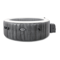
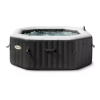
| Type | Inflatable |
| Outer Diameter | 2.01 m |
| Height | 0.71 m |
| Heating System | Yes |
| Included Accessories | Insulated cover, inflation hose, carry bag |