195A
SAVE THESE INSTRUCTIONS
(195IO) SAND FILTER PUMP ENGLISH 7.5” X 10.3” PANTONE 295U 07/17/2013
English
Page 9
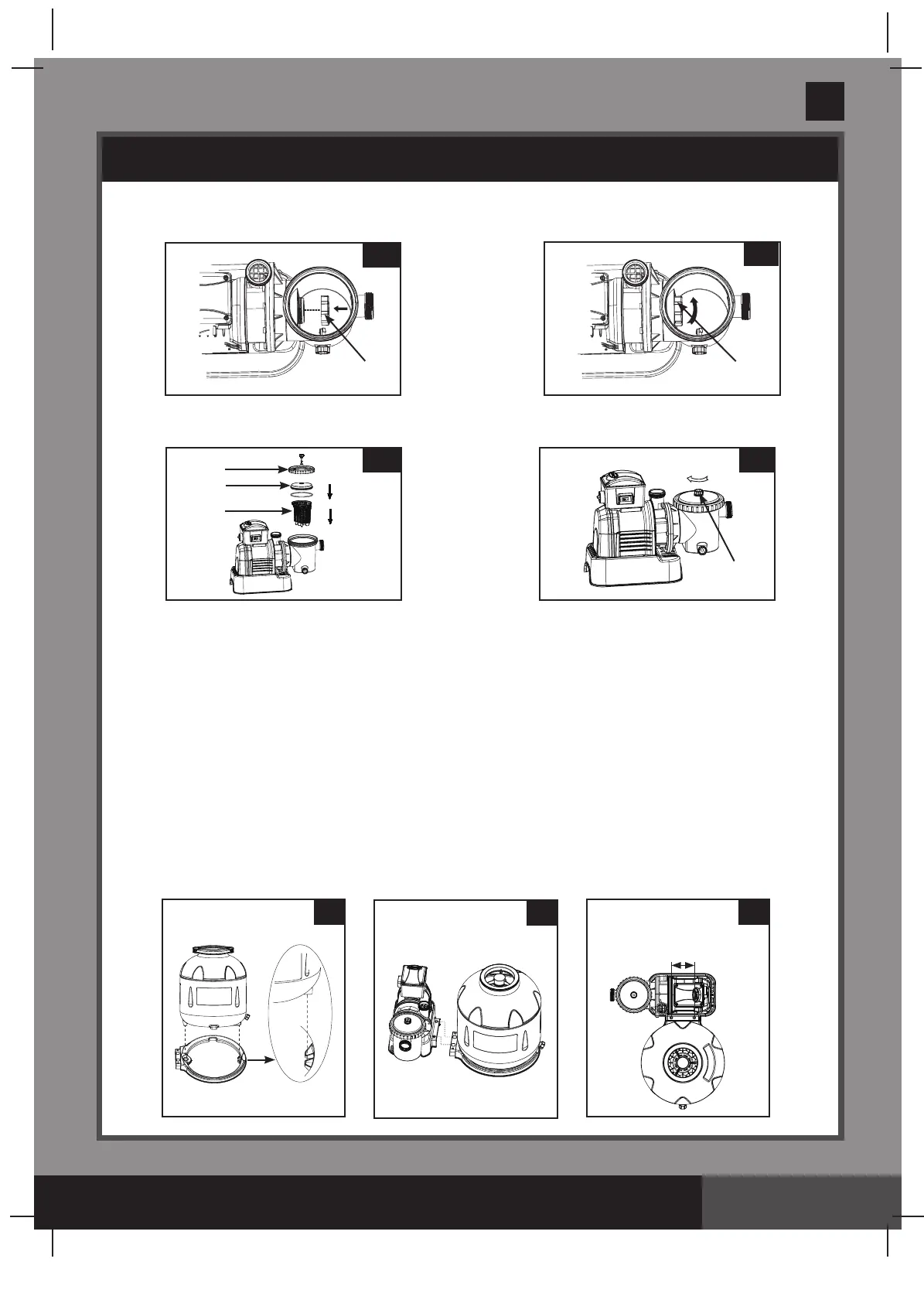
4. In a clockwise motion screw filter housing nut (17) onto the motor water inlet (See
drawings 12.1 & 12.2).
5. Replace the basket (16) and leaf trap cover (14) back to the pre-filter housing (See
drawings 13.1 & 13.2).
SETUP INSTRUCTIONS (continued)
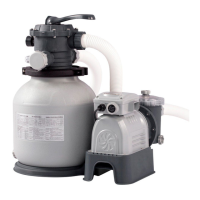
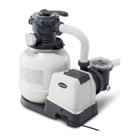
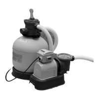
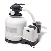
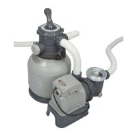
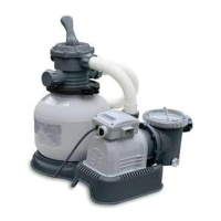
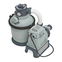
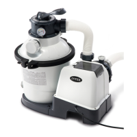
Sand tank installation:
1. Place the tank support base at the selected location.
2. Place the tank on the tank support base (See drawing 14.1).
3. Connect the motor pre-filtering assembly unit to the tank support base (See drawing 14.2).
NOTE: Ensure the pre-filter housing water inlet hose connection is facing towards the pool.
IMPORTANT: Some countries, especially in the European community, require the
product to be secured to the ground or to a base in a permanent upright position.
Check your local authorities to determine if there is a regulation in your area
regarding above-the-ground swimming pool filter-pumps. If yes, then the product
can be mounted to a platform using the two holes located in the base.
See drawing 14.3.
The product can be mounted on a cement base or onto a wooden plat form to
prevent accidental falling over.
• Themountingholesare6.4mmindiameterandspaced100mmformodel
SF80220 (spaced 115 mm for model SF70220 & SF60220) apart.
• Usetwoboltsandlocknutswithamaximumof6.4mmindiameter.
12.1
17
12.2
17
13.213.1
14
16
35
14.1
14.2
14.3
Model SF80220: 100 mm
Model SF70220 & SF60220: 115 mm
19