j | BA 14.0168 | 10/2013
7
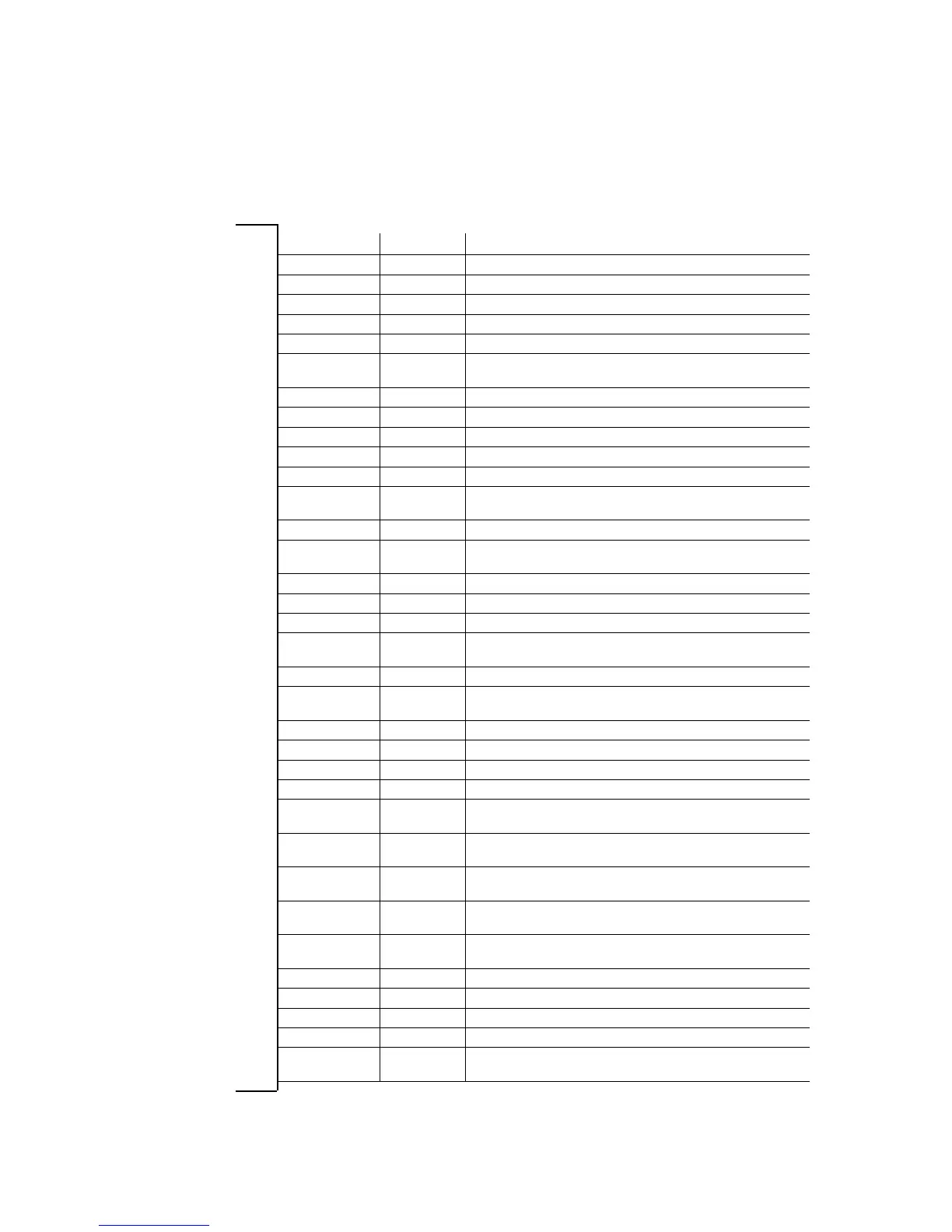
1.4 Abbreviations used
Letter symbol Unit Name
I A Current
I
H
A Holding current, at 20 °C and withstand voltage
I
L
A Release current, at 20 °C and release voltage
I
N
A Rated current, at 20 °C and rated voltage
M
A
Nm Tightening torque of the fixing screws
M
K
Nm Characteristic torque of the brake, characteristic value of a relative
speed of 100 rpm
n
max
rpm Maximum occurring speed during the slipping time t3
P
H
W Coil power during holding, at voltage change-over and 20 °C
P
L
W Coil power during release, at voltage change-over and 20 °C
P
N
W Rated coil power, at rated voltage and 20 °C
Q J Quantity of heat/energy
Q
E
J Maximally permissible friction energy for one-time switching,
thermal parameter of the brake
Q
R
J Braking energy, friction energy
Q
Smax
J Maximally permissible friction energy for cyclic switching, depending
on the operating frequency
R
m
N/mm
2
Tensile strength
R
N
Ohms Rated coil resistance at 20 °C
R
z
μm Averaged surface roughness
S
h
1/h Operating frequency, i.e. the number of switching operations evenly
spreadoverthetimeunit
S
hue
1/h Transition operating frequency, thermal parameter of the brake
S
hmax
1/h Maximally permissible operating frequency, depending on the
friction energy per switching operation
s
L
mm Air gap, i.e. lift of the armature plate while the brake is switched
s
LN
mm Rated air gap
s
Lmin
mm Minimum air gap
s
Lmax
mm Maximum air gap
t
1
ms Engagement time, sum of the delay time and braking torque
rise time t
1
=t
11
+t
12
t
2
ms Disengagement time, time from switching the stator until reaching
0.1 M
rated
t
3
ms Slipping time, operation time of the brake (according to t
11
)until
standstill
t
11
ms Delay time during engagement, time from voltage switch-off
to the start of torque rise
t
12
ms Rise time of the braking torque, time from the start of torque rise
until reaching the braking torque
t
ue
s Overexcitation time
U V Voltage
U
H
VDC Withstand voltage, during voltage change-over
U
L
VDC Release voltage, during voltage change-over
U
N
VDC Rated coil voltage; in the case of brakes requiring a voltage
change-over, U
rated
equals U
L