77
2. Count the number of exposed threads and repeat this
procedure for the opposite shock.
3. Proceed to STEP 9 in
HEIGHT ADJUSTMENT OF
STABILIZERS in this procedure of the manual.
REMOVING/INSTALLING GEARBOX
(FIGURE 12)
CAUTION
Perform the following procedure in a des-
ignated work area to prevent damage to
flooring (carpeting, tile, etc.).
Removing
1. Remove the drive wheels from the wheelchair. Refer to
REMOVING/INSTALLING DRIVE WHEELS in PRO-
CEDURE 12 of this manual.
2. Remove the drive wheel hub from the existing gearbox
drive shaft. Refer to
REMOVING/INSTALLING DRIVE
WHEEL HUBS in PROCEDURE 12 of this manual.
NOTE: Note the mounting position of gearbox to the sus-
pension arm before gearbox disassembly.
3. Remove the four (4) mounting screws that secure the
motor/gearbox to the suspension arm.
4. If necessary, remove existing motor from gearbox. Re-
fer to
REMOVING/INSTALLING THE MOTOR in PRO-
CEDURE 12 of this manual.
5. If necessary, install existing motor onto NEW gearbox.
Refer to
REMOVING/INSTALLING THE MOTOR in
PROCEDURE 12 of this manual.
Installing
WARNING
When reinstalling the gearbox ALWAYS use
the mounting holes furthest back on the sus-
pension arm. DO NOT reposition the motors.
CAUTION
The FRONT mounting screws that secure the
gearbox to the suspension arm MUST be 5/
16-18 x 2-1/2-inches long and the REAR hex
screws that secure the gearbox to the sus-
pension arm MUST be 5/16-18 x 1-1/4-inches
long. Otherwise damage to the gearbox
casting can result.
1. Position the NEW gearbox with the mounting holes fur-
thest back on the suspension arm.
2. When reassembling the gearbox to the suspension arm,
use Loctite 242 and torque mounting screws to 160-
inch pounds.
NOTE: Replace any parts that show signs of wear or dam-
age.
3. Reinstall the drive wheel hub to the new gearbox drive
shaft. Refer to
REMOVING/INSTALLING DRIVE
WHEEL HUBS in PROCEDURE 12 of this manual.
4. Reinstall the drive wheels onto the wheelchair. Refer to
REMOVING/INSTALLING DRIVE WHEELS in PRO-
CEDURE 12 of this manual.
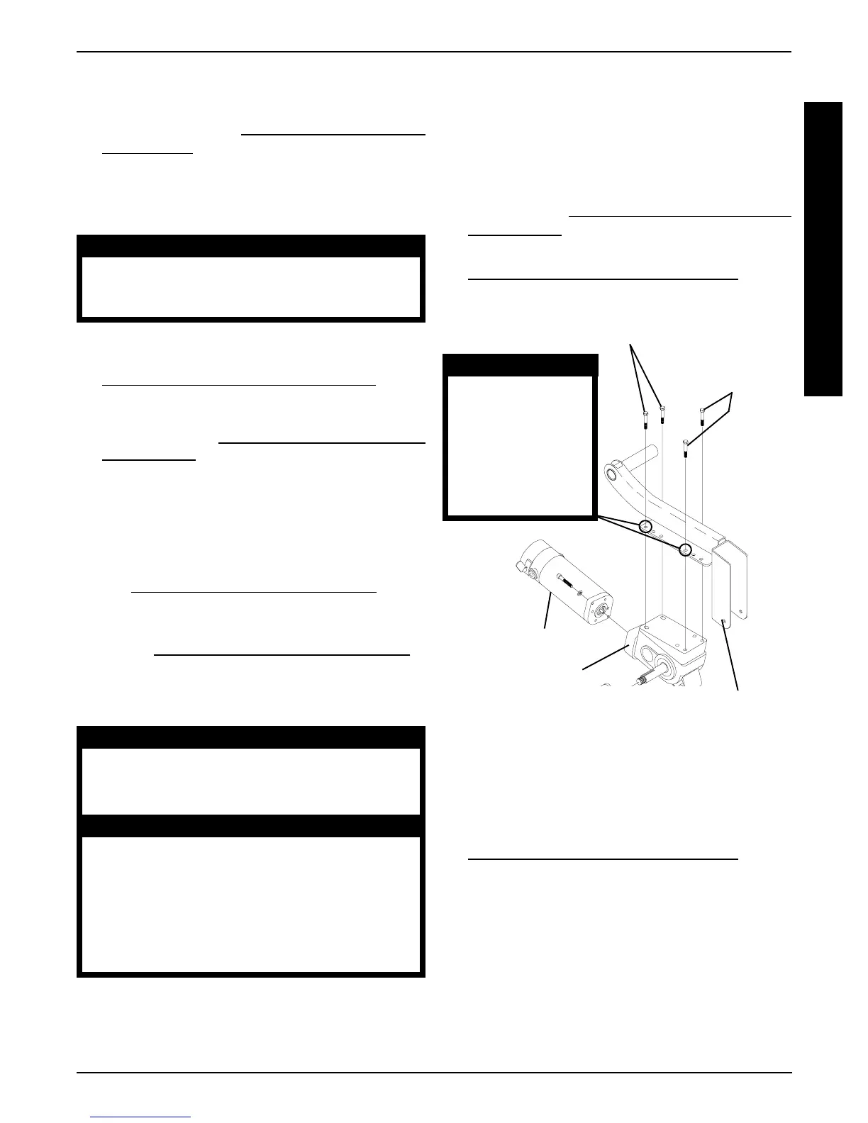
FIGURE 12 - REMOVING/INSTALLING GEARBOX
5/16-18 x 2-1/2-inch
Mounting Screws
5/16-18 x 1-1/4-inch
Mounting Screws
Gearbox
Suspension Arm
Motor
WARNING
When reinstalling the
gearbox ALWAYS
use the mounting
holes furthest back
on the suspension
arm. DO NOT reposi-
tion the motors.
REPLACING SUSPENSION ARM
(FIGURE 13)
1. Remove the drive wheels from the wheelchair. Refer to
REMOVING/INSTALLING DRIVE WHEELS in PRO-
CEDURE 12 of this manual.
2. Perform one (1) of the following:
A. (GROUP 24) - Loosen the mounting screws that
secures the wiring harness and the battery sub-
frame to the base frame assembly.
B. (GROUP 22) - Loosen the two (2) mounting
screws that secures the rear of the battery tray to
the sub-frame assembly.
PROCEDURE 15MWD WHEELCHAIRS
M
W
D
W
H
E
E
L
C
H
A
I
R
S