93
FWD WHEELCHAIRS PROCEDURE 17
F
W
D
W
H
E
E
L
C
H
A
I
R
S
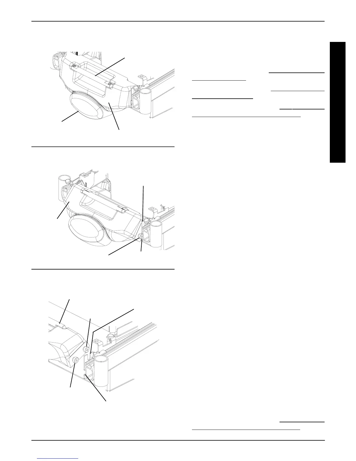
FIGURE 4 - REMOVING/INSTALLING
COUNTERWEIGHT
Bottom Shoulder Screw
Bottom Slot in Mounting Bracket
Top Shoulder
Screw
Counterweight
DETAIL “C” - REMOVING - STEP 4;
INSTALLING - STEP 2
DETAIL “B” - REMOVING - STEP 3;
INSTALLING - STEPS 3, 4
DETAIL “A” - REMOVING - STEP 2;
INSTALLING - STEP 5
Outside
Lower Edge
Handle
Bottom Shoulder Screw
Mounting Bracket
Top Slot in
Mounting
Bracket
REPLACING GROUP 24 BATTERY
BOX SUB-FRAME (FIGURE 5)
Removing
1. Remove the rear shroud. Refer to
REMOVING/INSTALL-
ING REAR SHROUD in this procedure of the manual.
2. Remove the counterweight. Refer to
REMOVING/INSTALL-
ING COUNTERWEIGHT in this procedure of the manual.
3. Remove the battery boxes. Refer to
INSTALLING/RE-
MOVING GROUP 24 BATTERY BOXES in PRO-
CEDURE 9 of this manual.
4. Cut tie wrap A, which secures the sensor cable AND
the LEFT motor cable to the battery box sub-frame.
5. Cut tie-wrap B, which secures the battery charger cable
AND the RIGHT motor cable to the battery box sub-frame.
6. Remove the two (2) mounting screws and locknuts
that secure the wiring harness w/bracket to the bat-
tery box sub-frame.
7. Remove the wiring harness w/bracket from the bat-
tery box sub-frame.
8. Remove the four (4) mounting screws and washers
that secure the battery box sub-frame to the mount-
ing brackets.
9. Remove the EXISTING sub-frame assembly.
10. Remove the four (4) mounting screws and wash-
ers that secure the two (2) mounting brackets to
the sub-frame.
11. Install the four (4) mounting screws and washers
that secure the two (2) NEW mounting brackets
to the sub-frame.
12. Install the four (4) mounting screws that secure the
NEW battery box sub-frame to the mounting brack-
ets. Use Loctite 242 and torque mounting screws to
156-inch pounds.
13. Install the two (2) mounting screws and locknuts that
secure the wiring harness w/bracket to the NEW bat-
tery box sub-frame. Use Loctite 242 and torque mount-
ing screws to 160-inch pounds.
14. Secure the sensor cable AND the LEFT motor cable
to the NEW battery box sub-frame using tie wrap A.
Refer to FIGURE 5 for tie wrap positioning.
15. Secure the battery charger cable AND the RIGHT
motor cable to the NEW battery box sub-frame using
tie wrap B. Refer to FIGURE 5 for tie wrap positioning.
16. Reinstall the battery boxes. Refer to
INSTALLING/RE-
MOVING GROUP 24 BATTERY BOXES in PRO-
CEDURE 9 of this manual.
Counterweight
Counterweight
Bottom
Slot