67
Matrix Mono
Part 3 - Installaon and Field Sengs
Matrix Mono
66
Inventor Matrix Mono Engineering Data Book
2.8 Drainage
Drainage ditch should be provided to allow drainage of condensate that may form on the air side heat exchanger when
the unit is running in heating mode or domestic hot water mode. The drainage should ensure that condensate is directed
away from roadways and footpaths, especially in locations where the climate is such that condensate may freeze.
Figure 3-2.6: 4/6kW models drainage hole
Figure 3-2.7: 8/10/12/14/16kW models drainage hole
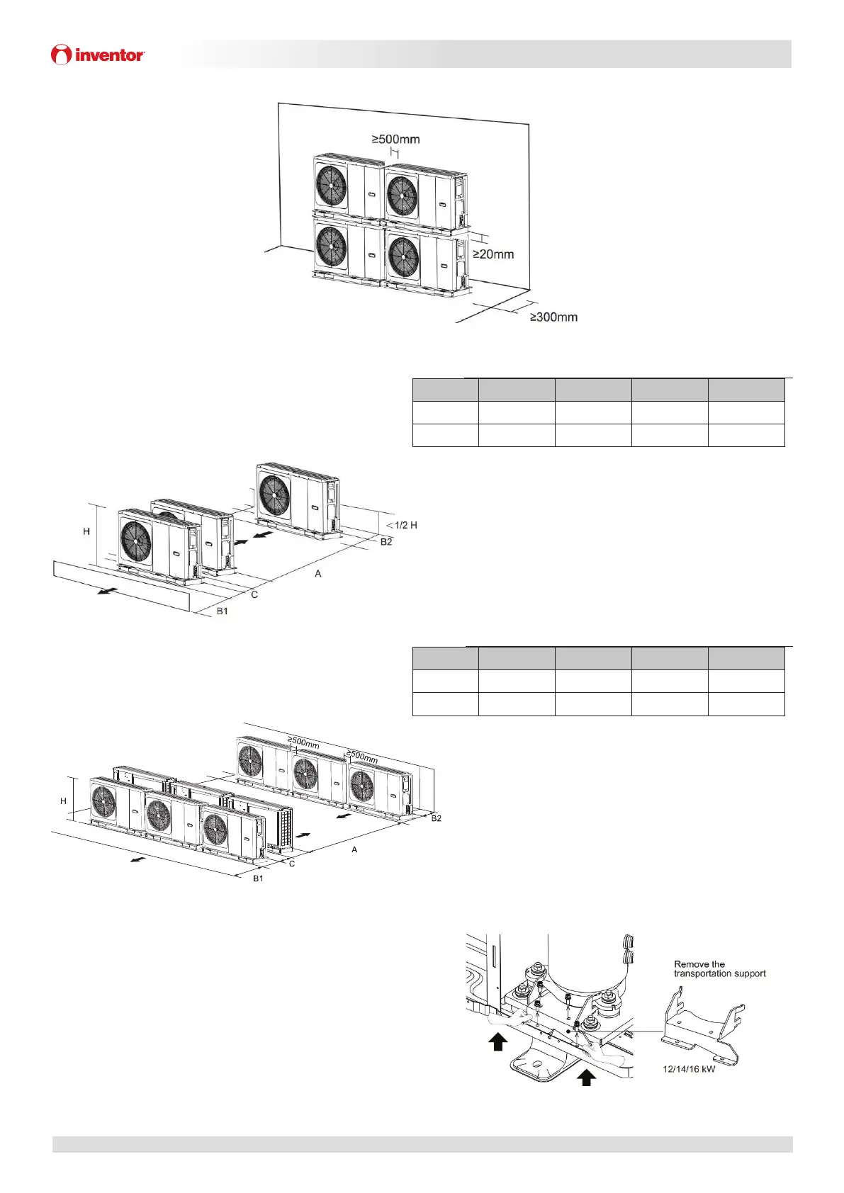
2.9 Spacing
1.1.1 Stacked installation
Outdoor units must be spaced such that sufficient air may flow through each unit. Sufficient airflow across heat
exchangers is essential for outdoor units to function properly. Figures 3-2.8 and 3-2.9 show the minimum spaces that must
be allowed between units and the minimum distances from obstacles in front of and behind units.
Figure 3-2.8: Installation with obstacles in front of the unit Table 3-2.2: Minimum spacing from obstacles in front of the unit
Model A(mm)
4-6KW
≥1000
8-16KW
≥1500
Matrix Mono
67
Part 3 - Installation and Field Settings
Figure 3-2.9: Installation with obstacles behind the unit
1.1.2 Installation in Rows
Figure 3-2.10: Single row installation Table 3-2.3: Single row installation spacing requirements
Model A(mm) B1(mm) B2(mm) C(mm)
4-6KW
≥1500 ≥500 ≥150 ≥300
8-16KW
≥2000 ≥1000 ≥150 ≥300
Figure 3-2.11: Multi-row installation Table 3-2.4: Multiple row installation spacing requirements
Model A(mm) B1(mm) B2(mm) C(mm)
4-6KW
≥2500 ≥1000 ≥300 ≥600
8-16KW
≥3000 ≥1500 ≥300 ≥600
Figure 3-2.12: Remove the transportation support
2.10 Transportation support
For 12/14/16kW model, there is a transportation support which is
used to protect tubes from breaking during transportation and
this support should be taken off before turning on the heat pump.
 Loading...