69
Matrix Mono
Part 3 - Installaon and Field Sengs
Matrix Mono
68
Inventor Matrix Mono Engineering Data Book
3 Water Pipework
3.1 Water Circuit Checks
Matrix Mono units are equipped with a water inlet and outlet for connection to a water circuit. Matrix units should only
be connected to closed water circuits. Connection to an open water circuit would lead to excessive corrosion of the
water piping. Only materials complying with all applicable legislation should be used.
Before continuing installation of the unit, check the following:
The maximum water pressure ≤ 3 bar.
The maximum water temperature ≤ 70°C according to safety device setting.
Always use materials that are compatible with the water used in the system and with the materials used in the unit.
Ensure that components installed in the field piping can withstand the water pressure and temperature.
Drain taps must be provided at all low points of the system to permit complete drainage of the circuit during
maintenance.
Air vents must be provided at all high points of the system. The vents should be located at points that are easily
accessible for service. An automatic air purge is provided inside the unit. Check that this air purge valve is not
tightened so that automatic release of air in the water circuit is possible.
3.2 Water Volume and Expansion Vessel Pre-pressure Checks
The units are equipped with an expansion vessel of 8L that has a default pre-pressure of 1.5 bar. To assure proper
operation of the unit, the pre-pressure of the expansion vessel might need to be adjusted.
Check that the total water volume in the installation, excluding the internal water volume of the unit, is at least 40L.
Expansion vessel volume must fit the total water system volume.
To size the expansion for the heating and cooling circuit.
The expansion vessel volume can follow the figure below:
Figure 3-3.1: Expansion vessel volume
Notes:
In most applications this minimum water volume will be satisfactory.
In critical processes or in rooms with a high heat load though, extra water might be required.
When circulation in each space heating loop is controlled by remotely controlled valves, it is important that this
minimum water volume is kept even if all the valves are closed.
Matrix Mono
69
Part 3 - Installation and Field Settings
3.3 Water Circuit Connection
Water connections must be made correctly in accordance with the labels on the outdoor unit, with respect to the water
inlet and water outlet. If air, moisture or dust gets in the water circuit, problems may occur. Therefore, always take into
account the following when connecting the water circuit:
Use clean pipes only.
Hold the pipe end downwards when removing burrs
Cover the pipe end when inserting it through a wall to prevent dust and dirt entering.
Use a good thread sealant for sealing the connections. The sealing must be able to withstand the pressures and
temperatures of the system.
When using non-copper metallic piping, be sure to insulate the two kind of materials from each other to prevent
galvanic corrosion.
For copper is a soft material, use appropriate tools for connecting the water circuit. Inappropriate tools will cause
damage to the pipes
3.4 Water Circuit Anti-freeze Protection
Ice formation can cause damage to the hydronic system. As the outdoor unit may be exposed to sub-zero temperatures,
care must be taken to prevent freezing of the system. All internal hydronic parts are insulated to reduce heat loss.
Insulation must also be added to the field piping.
The software contains special functions using the heat pump to protect the entire system against freezing.
When the temperature of the water flow in the system drops to a certain value, the unit will heat the water, either
using the heat pump, the electric heating tap, or the backup heater. The freeze protection function will turn off only
when the temperature increases to a certain value.
In event of a power failure, the above features would not protect the unit from freezing.
Since a power failure could happen when the unit is unattended, the supplier recommends use anti-freeze fluid to
the water system.
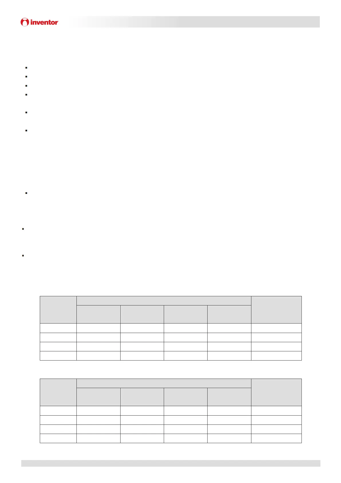
Depending on the expected lowest outdoor temperature, make sure the water system is filled with a concentration
of glycol as mentioned in the table below. When glycol is added to the system, the performance of the unit will be
affected. The correction factor of the unit capacity, flow rate and pressure drop of the system is listed in the table
3-3.1 and 3-3.2.
Table 3-3.1: Ethylene Glycol
Concentration
of ethylene
glycol (%)
Modification coefficient
Minimum outdoor
temperature(°C)
Cooling capacity
modification
Power input
modification
Water resistance
Water flow
modification
0 1.000 1.000 1.000 1.000 0
10 0.984 0.998 1.118 1.019 -5
20 0.973 0.995 1.268 1.051 -15
30 0.965 0.992 1.482 1.092 -25
Table 3-3.2: Propylene Glycol
Concentration
of propylene
glycol (%)
Modification coefficient
Minimum outdoor
temperature(°C)
Cooling capacity
modification
Power input
modification
Water resistance
Water flow
modification
0 1.000 1.000 1.000 1.000 0
10 0.976 0.996 1.071 1.000 -4
20 0.961 0.992 1.189 1.016 -12
30 0.948 0.988 1.380 1.034 -20
 Loading...