30
3.2 Connection of piping
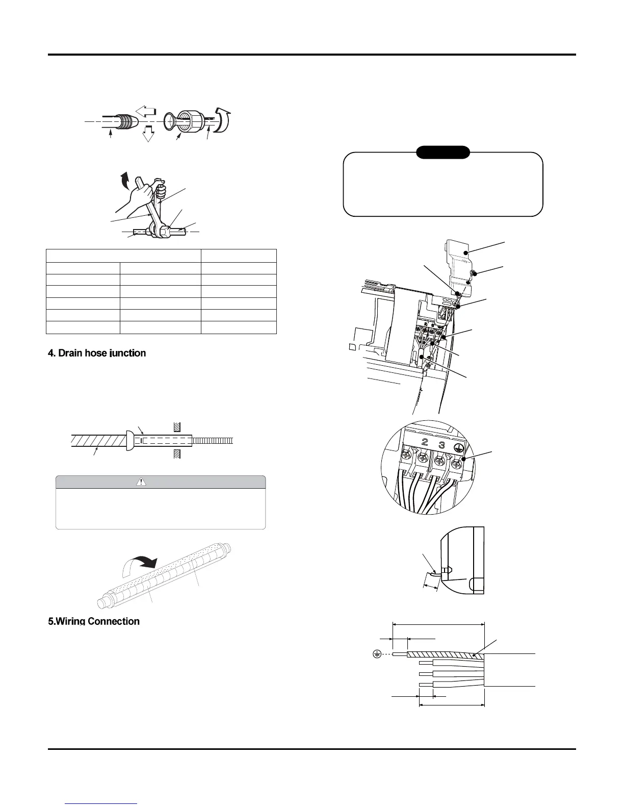
1.Align the center of the pipes and sufficiently tighten the flare nut
by hand.
2.Tighten the flare nut with a wrench.
If drain hose extension or embedded drain piping is required,
use appropriate parts that match the hose front end.
Insert drain hose into the handle of drain pan, and join
drain hose and connecting hose according to the figure by.
Wiring the connecting cable can be carried out ithout remov-
ing the front panel.
1. Remove the air inlet grille. Open the air inlet grille upward and
pull it toward you.
2. Remove the terminal cover and cord clamp.
3. Insert the connecting cable (or as according to local regula-
tions/codes) into the pipe hole on the wall.
4. Pull the connecting cable through the cable slot on the rear
panel so that it protrudes about 15 cm out of the front.
Insulation (Drain hose)
Drain hose
CAUTION
Insert the drain hose and drain cap into the drain port, mak-
ing sure that it comes in contact with the back of the drain
port, and then mount it. If the drain hose is not connected
properly, leaking will occur.
• Attach the Insulation (Drain hose) to the drain hose.
CAUTION
Indoor unit tubing Flare nut Pipes
Wrench
Indoor unit tubing
Open-end wrench (fixed)
Connection pipe
Flare nut
mm inch kg
.
m
Ø6.35 1/4 1.8
Ø9.52 3/8 4.2
Ø12.7 1/2 5.5
Ø15.88 5/8 6.6
Ø19.05 3/4 6.6
Outside diameter Torque
Shield pipe
Extension drain hose
Inside the room
Drain hose
5. Insert the connecting cable fully into the terminal block and
secure it tightly with screws.
6. Tightening torque: 1.2 N•m (0.12 kgf•m).
7. Secure the connecting cable with the cord clamp.
8. Attach the terminal cover, rear plate bushing and air inlet grille
on the indoor unit.
Screw
Screw
Terminal cove
e sure to refer to the iring system diagram
labeled inside the front panel.
Check local electrical regulations for any
specific iring instructions or limitations.
CAUTION
Installation Manual
 Loading...