31
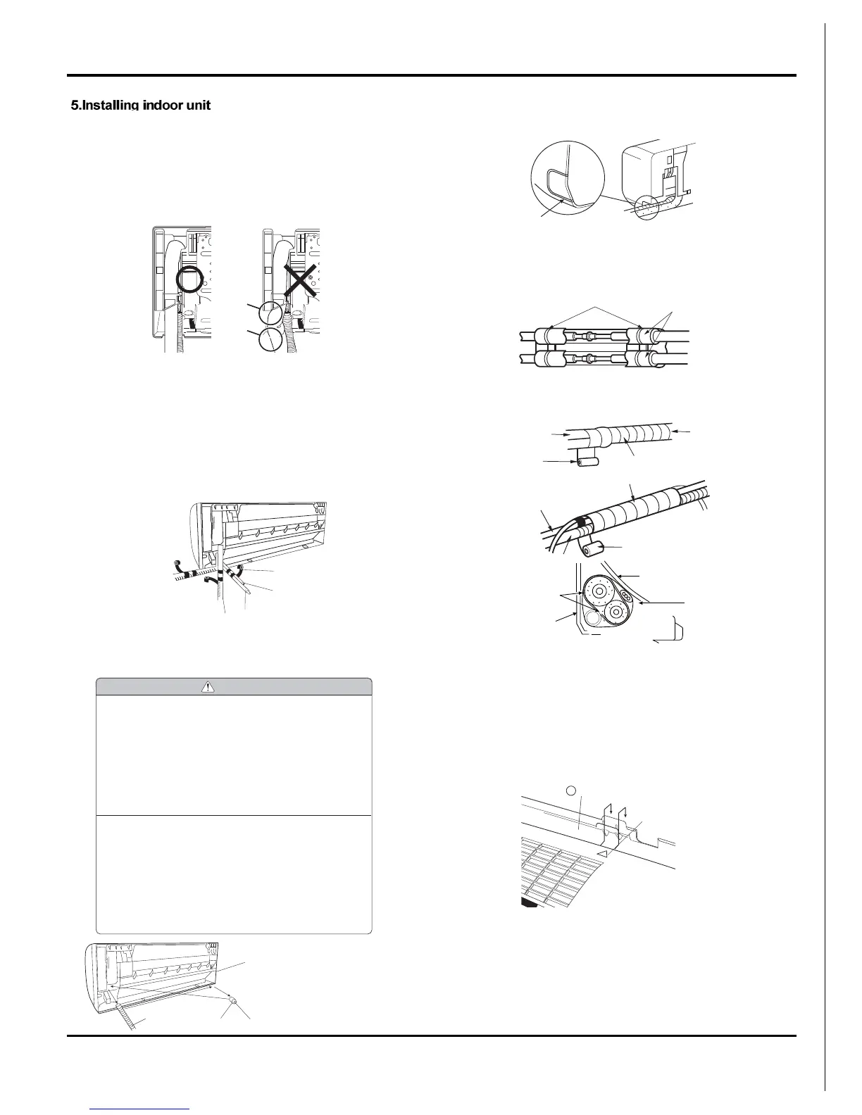
1.After making slits on the front panel with a knife or similar tool,
cut them out with a pair of nippers or an equivalent tool.
2.Overlap the connection pipe insulation material and the indoor
unit pipe insulation material. Bind them together with vinyl tape
so that there is no gap.
3.Wrap the area which accommodates the rear piping housing
section with vinyl tape.
4.Bundle the piping and drain hose together by wrapping them
with vinyl tape for enough to cover where they fit into the rear
piping housing section.
Indoor unit installation
1) Pass the drain hose and refrigerant pipes through the wall
hole, then set the indoor unit on the mounting plate hooks by
using the markings at the top of the indoor unit as a guide.
2) Swing the indoor unit to right and left to confirm that it is firmly
hooked on the installation plate.
3)While pressing the indoor unit onto the wall, hook it at the
lower part on the installation plate.
Pull the indoor unit toward you to confirm that it is firmly
hooked on the installation plate.
In the case of bending or curing refrigerant pipes, keep the fol-
lowing precautions in mind.
Abnormal sound may be generated if improper work is conducted.
1) Do not strongly press the refrigerant pipes onto the bottom
frame.
2) Do not strongly press the refrigerant pipes on the front grille,
either.
The piping can be lead out from right, right rear, left left rear.
Right-side, right-back, or right-bottom piping
1)After making slits on the front panel with a knife or similar tool,
cut them out with a pair of nippers or an equivalent tool.
Attach the drain hose to the underside of the refrigerant pipes
with an adhesive vinyl tape.
2) Wrap the refrigerant pipes and drain hose together with an
insulation tape.
eft-side, left-back, or left-bottom piping
• Interchange the drain cap and the drain hose.
1)
2)
Right piping
Bind with vinyl tape
Indoor unit drain hose
(bottom)
Pipe (top)
Rear piping
Bottom
piping
Drain cap
Indoor unit
drain hose
Remove the drain cap by pulling
at the projection at the end of
the cap with pliers, etc.
For left outlet piping, cut off the
piping outlet cutting groove
with a hacksaw.
CAUTION
(1) In order to align the drain hose and drain cap, be
sure to insert securely and vertically. Incline inser-
tion will cause water leakage.
(2) When inserting, be sure not to attach any material
besides water. If any other material is attached, it
will cause deterioration and water leakage.
(3) After removing drain hose, be sure not to forget
mounting drain cap.
(4) Be sure to fix the drain hose with tape to the bottom
of piping.
(5) Prevent drain water frozen under low tempera-
ture environment.
When installing indoor unit's drain hose outdoors, necessary
measure for frost protection should be taken to prevent drain
water frozen.
• Under low temperature environment (when outdoor tem-
perature under 32 °F), after cooling operation is executed,
water in the drain hose could be frozen.
Once drain water is frozen, the drain hose will be blocked
and water leakage may be resulted for indoor unit.
Slit
Plastic bands
Insulation material
Connection
pipe
Vinyl tape
(wide)
Wrap with vinyl tape
Indoor
unit pipe
Wrap with vinyl tape
Drain hose
Pipe
Vinyl tape(wide)
Installation
plate
Indoor unit
Connecting
cable
 Loading...