Page 11
Page 10
Step 2: Unfastening the operation panel and
detaching the lter
1. Open the packaging and take out the indoor
unit. Remove the protective tape and any
components.
2.
3.
4.
Remove all of the accessories.
1. Measure the position of the holes for
installation.
2. Insert the M8 bolts into the unit while it is on
the oor (the amount of bolts used depends
on the number of holes on the unit's chassis).
3. Lift up the indoor unit so that the installation
holes cover the bolts, then fasten the nuts
onto the bolts and tighten them.
Check that all of the accessories match those
found on the “Installation Diagrams and
Accessories” as shown on the previous page.
Step 3. Fastening the indoor unit (to prevent
it from falling down)
NOTE: To prevent the unit from falling
down, the indoor unit must be fastened
on the oor by the bolts.
1. Lay the connecting piping at on the ground.
Place the drainage hose, refrigerant pipe, and
all electrical wiring (making sure that both
ends are arranged correctly) next to the
piping.
2.
Using the drainage hose as a guide, measure
and adjust the length of the low voltage
wiring, high voltage wiring, any other electrical
wiring, and refrigerant pipe. Use cable ties to
initially fasten them in place.
3. Arrange the piping so that the drainage hose
is on the bottom, the connecting piping is in
the middle, and the electrical wiring is at the
top.
Step 4. Piping and binding
CAUTION
• Take out the protective wedge and measure
the correct size.
• Use the self-tapping screws to fasten the
protective wedge to the top cover of the
indoor unit.
• Fasten the other end of the wedge tightly
to the wall using the self-tapping screws.
If further support is needed to prevent the unit
from falling down, a protective wedge can be
installed. The installation procedure for this
wedge is as follows:
Take out the PM2.5 lter and install it.
Fig. 4.3
4. According to the place of the indoor unit and
the hole in the wall, adjust the direction and
place of hoses (See Fig.4.5) to determine
discharging from left or right.
drainage
electrical wiring
refrigerant pipe
5. Lay the machine’s packaging on the ground.
Place the unit face down to the packaging.
Undo the screws on the back cover, then hold
the hook and pull the cover out. Undo the
screws of the terminal block’s cover, then
remove the cover along the direction of arrow.
back cover
screw
handle
plastic panel for
covering the power
cords
for 24000Btu/h
model
for 18000Btu/h
model
clamp base
connecting
pipe and
drainage
hose
screw
cover of
terminal block
terminal block
power cord and
connecting wire
cord clamp
piping joint
power cord
right exit
left exit
6. Remove the cable for test and match the wire
colors /labels with the labels on the terminal
block. Use cord clamp and screws to fasten the
wires to the terminal.
Fig. 4.4
Fig. 4.6
Step 5: Applying the sealant putty and
installing the wall hole cover
1. Tidy up the already bound piping.
2. Evenly apply the sealant putty to the gaps
between the piping and the wall, then press
on the putty rmly.
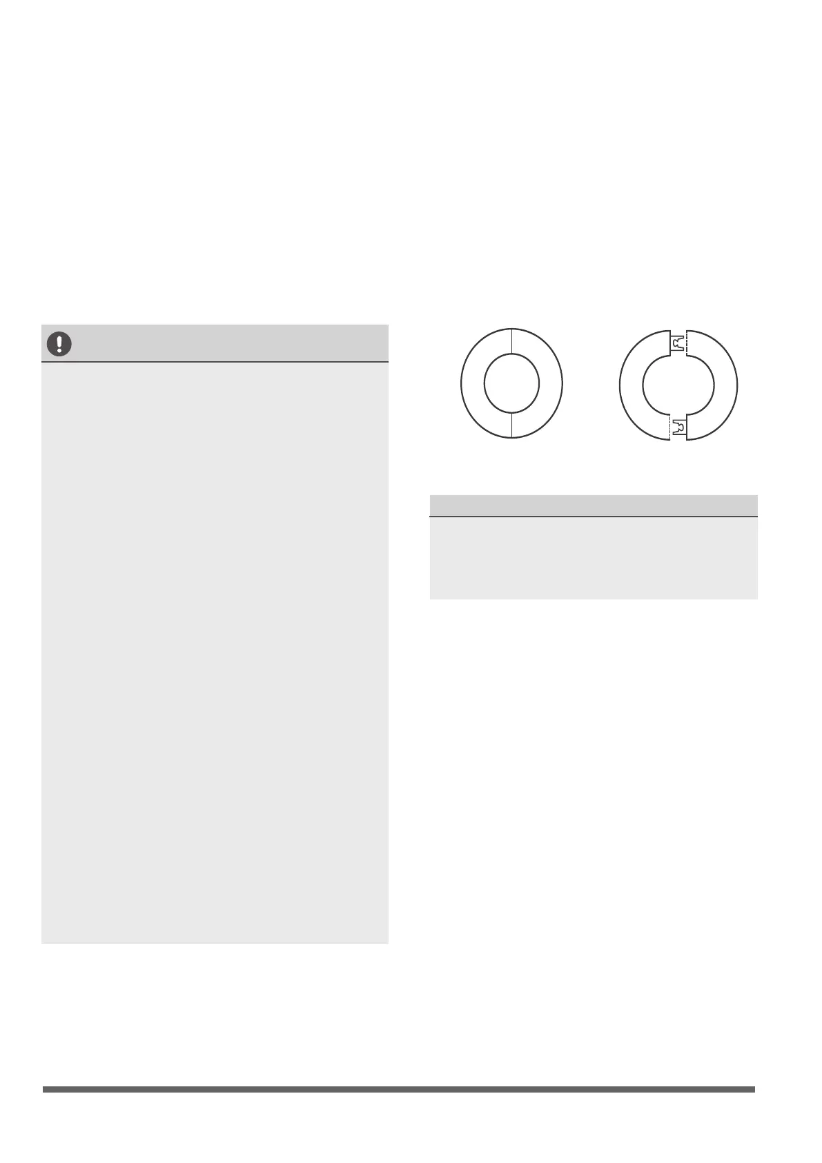
3. Pull the wall hole cover apart to open it.
After fastening tightly to the piping, push it
into the hole in the wall to securely fasten it
to the wall and complete the installation.
NOTE
•
When the unit is installed near the curtain,
please keep it at least 1m away from the
curtain to prevent the air intake from being
sheltered.
7.
Reinstall the terminal’s cover and x the cover
with screws. Set up the unit.
8. Bind the piping in order that the drainage hose
is on the bottom, the connecting piping is in
the middle, and the electrical wiring is at the top.
Do not wrap the joint of the connecting pipe
until the leak detection is nished.
9. According to the discharging place, use a nose
plier to remove a matching plastic panel, fasten
the wirings and pipes across the gap with the
cover on and screwed.
CAUTION
•
•
•
Use the cable ties to fasten the wirings and
pipes should keep away from the connecting
ends in case of leak detection.
When need to lengthen the drainage pipe,
please use a protecting tube to wrap the
indoor part of the extension, seal the
connector with contact glue. Any part of the
pipes should not be bending.
Be careful when place down or set up the
unit, prevent the surface from being
scratched.
Before removing the plastic panel, choose
the side from which the piping and wiring
will exit the unit. (a. Discharge from the
power side: remove the plastic panel of
power cord. B. For the 18000Btu/h model,
remove the plastic panel both of the power
and the 18000Btu/h side. C. For the
24000Btu/h model, remove the plastic panel
of the power side, 18000Btu/h side and
24000Btu/h side. ) If do not discharge from
the panel which is removed, the hole will not
be rat proof since without any block.
When bending the pipes, please note
intensity to prevent the pipes becoming at
or bend.
•
•
 Loading...