Page 20
b. Using wire strippers, strip the rubber jacket
from both ends of the signal cable to reveal
approximately 15cm (5.9”) of wire.
c.
Strip the insulation from the ends.
d. Using a wire crimper, crimp u-lugs on the
ends.
NOTE: When connecting the wires, strictly
follow the wiring diagram found inside the
electrical box cover.
2.
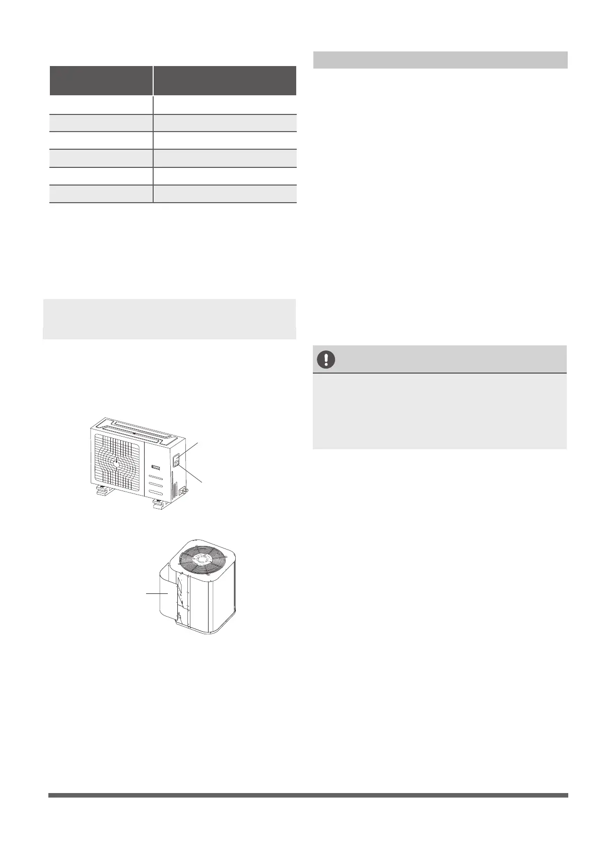
Remove the electric cover of the outdoor unit.
If there is no cover on the outdoor unit, take
off the bolts from the maintenance board and
remove the protection board.
(See Fig. 8.1, 8.2)
Cover
Screw
Fig. 8.1
Protection Board
Fig. 8.2
3.
Connect the u-lugs to the terminals
Match the wire colors/labels with the labels
on the terminal block, Firmly screw the u-lug
of each wire to its corresponding terminal.
4. Clamp down the cable with the cable clamp.
5.
Insulate unused wires with electrical tape.
Keep them away from any electrical or metal
parts.
6.
Reinstall the cover of the electric control box.
Indoor Unit Wiring
1.
Prepare the cable for connection
a. Using wire strippers, strip the rubber jacket
from both ends of the signal cable to reveal
about 15cm (5.9”) of the wire.
b.
Strip the insulation from the ends of the
wires.
c.
Using a wire crimper, crimp the u-lugs to
the ends of the wires.
2. Undo the screw on the cover of the electric
control box and remove the cover.
3.
Connect the u-lugs to the terminals.
Match the wire colors/labels with the labels
on the terminal block, Firmly screw the u-lug
of each wire to its corresponding terminal.
Refer to the Serial Number and Wiring
Diagram located on the cover of the electric
control box.
CAUTION
• While connecting the wires, please strictly
follow the wiring diagram.
• The refrigerant circuit can become very
hot. Keep the interconnection cable away
from the copper tube.
4.
Clamp down the cable with the cable clamp.
The cable must not be loose or pull on the
u-lugs.
5.
Reattach the electric box cover.
Table 8.2: Other World Regions
Rated Current of
Appliance (A)
Area (mm²)
Nominal Cross-Sectional
≤ 6 0.75
6 - 10 1
10 - 16 1.5
16 - 25 2.5
25- 32 4
32 - 45 6
Page 21
Air Evacuation
Safety Precautions
CAUTION
• Use a vacuum pump with a gauge reading
lower than -0.1MPa and an air discharge capacity
above 40L/min.
• The outdoor unit does not need vacuuming.
DO NOT open the outdoor unit’s gas and
liquid stop valves.
• Ensure that the Compound Meter reads
-0.1MPa or below after 2 hours. If after
three hours of operation and the gauge
reading is still above -0.1MPa, check if there
is a gas leak or water inside the pipe. If
there is no leakage, perform another
evacuation for 1 or 2 hours.
• DO NOT use refrigerant gas to evacuate the
system.
Evacuation Instructions
Before using manifold gauge and vacuum pump,
read their operation manuals to familiarize
yourself with how to use them properly.
Manifold Gauge
Compound gauge
-76cmHg
Low pressure valve
High pressure valve
Charge hose
Charge hose
Vacuum pump
Pressure gauge
Low pressure valve
Fig. 9.1
1.
Connect the charge hose of the manifold
gauge to service port on the outdoor unit’s
low pressure valve.
2.
Connect another charge hose from the
manifold gauge to the vacuum pump.
3.
Open the Low Pressure side of the manifold
gauge.Keep the High Pressure side closed.
4.
Turn on the vacuum pump to evacuate the
system.
5.
Run the vacuum for at least 15 minutes, or
until the Compound Meter reads -76cmHG
(-1x10⁵Pa).
6.
Close the Low Pressure side of the manifold
gauge, and turn off the vacuum pump.
7.
Wait for 5 minutes, then check that there has
been no change in system pressure.
NOTE: If there is no change in system pressure,
unscrew the cap from the packed valve (high
pressure valve). If there is a change in system
pressure, there may be a gas leak.
8.
Insert hexagonal wrench into the packed valve
(high pressure valve) and open the valve by
turning the wrench in a 1/4 counterclockwise
turn. Listen for gas to exit the system, then
close the valve after 5 seconds.
Flare nut
Cap
Valve stem
Fig. 9.2
9. Watch the Pressure Gauge for one minute to
make sure that there is no change in pressure.
The Pressure Gauge should read slightly higher
than atmospheric pressure.
10. Remove the charge hose from the service port.
11.
Using hexagonal wrench, fully open both the
high pressure and low pressure valves.
OPEN VALVE STEMS GENTLY
When opening valve stems, turn the hexagonal
wrench until it hits against the stopper. DO NOT
try to force the valve to open further.
12. Tighten valve caps by hand, then tighten it
using the proper tool.
9
 Loading...