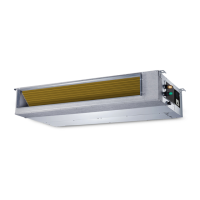
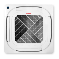
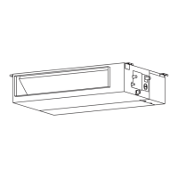
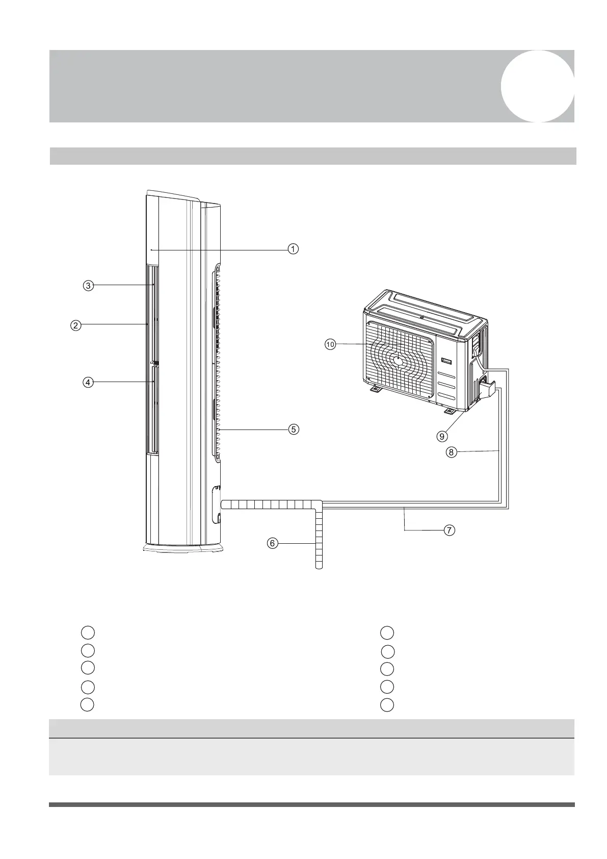
Illustrations in this manual are for explanatory purposes. The actual shape of your indoor unit may
Fig. 4.1
Page 9
Fig. 4.2
Indoor Unit Installation Instructions
PRIOR TO INSTALLATION
Before installing the indoor unit, refer to the
label on the product box to make sure that the
model number of the indoor unit matches the
model number of the outdoor unit.
Step 1: Select installation location
Before installing the indoor unit, you must
choose an appropriate location. The following
are standards that will help you choose an
appropriate location for the unit.
Proper installation locations meet the
following standards:
o Good air circulation
o Convenient drainage
o Positioned such that noise from the unit will
not disturb other people
o Firm and solid—the location will not vibrate
o Strong enough to support the weight of the
unit
o Positioned at least one meter from all other
electrical devices (e.g. TV, radio, computer)
DO NOT install unit in the following
locations:
Near any source of heat, steam, or
combustible gas
Near ammable items such as curtains or
clothing
Near any obstacle that might block air
circulation
Near the doorway
In a location subject to direct sunlight
NOTE ABOUT WALL HOLE:
If there is no xed refrigerant piping:
When choosing a location, be aware that
you should leave ample room for a hole in
the wall (see the step “Drill wall hole for
connective piping”) for the signal cable and
refrigerant piping that connect the indoor
and outdoor units. The default position for
all piping is the right side of the indoor unit
(while facing the unit). However, the unit
can accommodate piping to both the left or
the right.
Refer to the following diagram to ensure proper distance from walls and ceiling:
30cm (11.8in) or more
8cm (3.1in)
or more
200cm (78.7in)
or more
50cm (19.7in)
or more
50cm (19.7in)
or more
 Loading...