Page 14
NOTE:
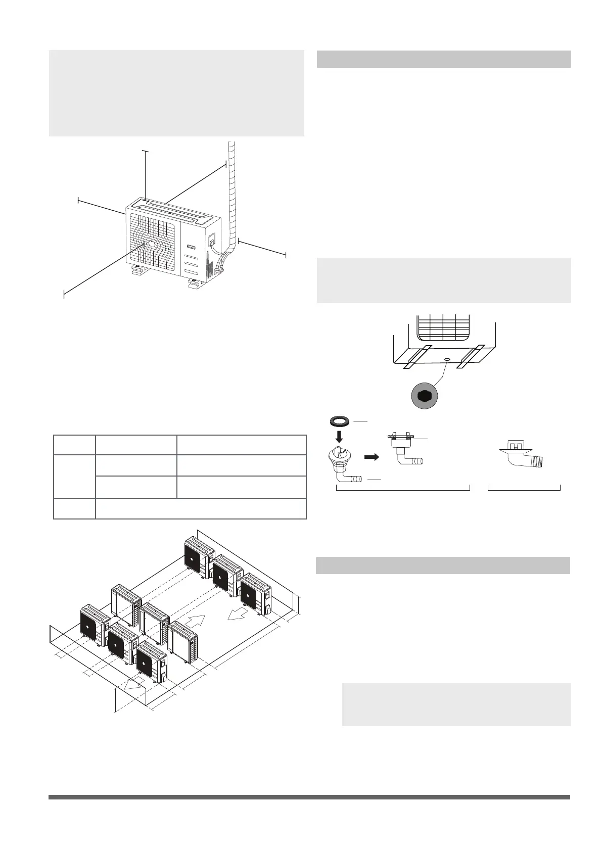
The minimum distance between the
outdoor unit and walls described in the
installation guide does not apply to airtight
rooms. Be sure to keep the unit unobstructed
in at least two of the three directions (M, N, P)
(See Fig. 5.10)
M
N
P
30 cm / 11.8” from back wall
60 cm / 23.6” above
30 cm / 11.8” on left
200 cm / 78” in front
Fig. 5.10
Drain Joint Installation
Before bolting the outdoor unit in place, you
must install the drain joint at the bottom of the
unit. (See Fig. 5.12)
1. Fit the rubber seal on the end of the drain
joint that will connect to the outdoor unit.
2. Insert the drain joint into the hole in the
base pan of the unit.
3. Rotate the drain joint 90° until it clicks in
place facing the front of the unit.
4. Connect a drain hose extension (not
included) to the drain joint to redirect water
from the unit during heating mode.
NOTE: Make sure the water drains to a safe
location where it will not cause water damage
or a slipping hazard.
Seal
Drain joint
(A) (B)
Base pan hole of
outdoor unit
Seal
Fig. 5.12
Notes On Drilling Hole In Wall
You must drill a hole in the wall for the
refrigerant piping, and the signal cable that will
connect the indoor and outdoor units.
1.
Determine the location of the wall hole
based on the location of the outdoor unit.
2.
Using a 65-mm (2.5”) core drill, drill a hole
in the wall.
NOTE: When drilling the wall hole, make
sure to avoid wires, plumbing, and other
sensitive components.
3.
Place the protective wall cuff in the hole.
This protects the edges of the hole and will
help seal it when you nish the installation
Fig. 5.11
L
H
300 cm / 118” or more
A
60 cm / 23.6”
or more
150 cm / 59”
or more
25 cm / 9.8”
or more
25 cm / 9.8”
or more
Rows of series installation
L ≤ H
L ≤ 1/2H
L A
25 cm / 9.8” or more
1/2H < L ≤ H
30 cm / 11.8” or more
L > H
Can not be installed
Table 5.3 The relations between H, A and L
are as follows.
Page 15
The drainpipe is used to drain water from the
unit. Improper installation may cause unit and
property damage.
CAUTION
• Insulate all piping to prevent condensation,
which could lead to water damage.
• If the drainpipe is bent or installed
incorrectly, water may leak and cause a
malfunction of the water- level switch.
• In HEAT mode, the outdoor unit will
discharge water. Ensure that the drain hose
is placed in an appropriate area to avoid
water damage and slippage due to frozen
drain water.
• DO NOT pull the drainpipe forcefully as this
could cause it to disconnect.
NOTE ON PURCHASING PIPES
This installation requires a polyethylene tube
(outside diameter = 3.7-3.9cm, inside diameter
= 3.2cm), which can be obtained at your local
hardware store or from your dealer.
Indoor Drainpipe Installation
1.
Make sure the drain pipe is connected to the
outdoor side downward.
2.
The hard polyvinyl chloride(PVC)plastic pipe
(external diameter 26 mm) sold in the market
is suitable for the attached soft drain pipe.
4. After the Drain Pipe has been connected,
please check if the water drains out of the
pipe efciently and has no leakage.
5. Refrigerant Pipe and Drain Pipe should be
heat-insulated to avoid condensing and
water-dropping later on.
3. Please connect the Soft Drain Pipe with the
Drain Pipe, then x it with band; if you have
to connect the Drain Pipe indoors, to avoid
condensing caused by air intake, you must
cover the pipe with heat-insulation material
(polyethylene with Specic Gravity of 0.03, at
least 9 mm in thickness), and use Glue Band
to x it.
Fig. 6.1
Drainpipe Installation
6
6.
Using a 65-mm (2.5”) core drill, drill a hole in
the wall. Make sure that the hole is drilled at a
slight downward angle, so that the outdoor
end of the hole is lower than the indoor end
by about 1cm (0.4”). This will ensure proper
water drainage (See Fig. 6.2). Place the
protective wall cuff in the hole. This protects
the edges of the hole and will help seal it
when you nish the installation process.
Fig. 6.2
NOTE: When drilling the wall hole, make sure
to avoid wires, plumbing, and other sensitive
components.
7. Pass the drain hose through the wall hole.
Make sure the water drains to a safe location
where it will not cause water damage or a
slipping hazard.
NOTE: The drainpipe outlet should be at least
5cm (1.9”) above the ground. If it touches the
ground, the unit may become blocked and
malfunction. If you discharge the water directly
into a sewer, make sure that the drain has a U
or S pipe to catch odors that might otherwise
come back into the house.
Drain pipe
Drain pipe
Glue
Band for covering the pipe
Wall
Outdoor
≈ 0.5~1cm
/ 0.2~0.4 inch
mc02

 Loading...