12 | Optidrive ODE-3 User Guide | Version 2.00 www.invertekdrives.com
3.6. Guidelines for mounting (IP66 Units)
Before mounting the drive, ensure that the
chosen location meets the environmental
condition requirements for the drive shown
in section 9.1. Environmental.
The drive must be mounted vertically,
on a suitable flat surface.
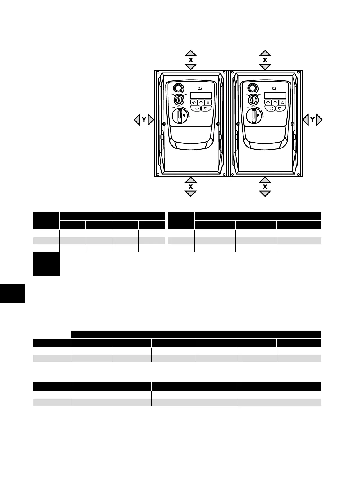
The minimum mounting clearances
as shown in the table below must be
observed.
The mounting site and chosen mountings
should be sufficient to support the weight
of the drives.
Using the drive as a template, or the
dimensions shown above, mark the
locations required for drilling.
Suitable cable glands to maintain the
ingress protection of the drive are required.
Gland holes for power and motor cables
are pre-moulded into the drive enclosure,
recommended gland sizes are shown
above. Gland holes for control cables
may be cut as required.
Drive
Size
X Above & Below Y Either Side
Drive
Size
Cable Gland Sizes
mm in mm in Power Cable Motor Cable Control Cables
1 200 7. 87 10 0.39 1 M20 (PG13.5) M20 (PG13.5) M20 (PG13.5)
2 200 7. 87 10 0.39 2 M25 (PG21) M25 (PG21) M20 (PG13.5)
3 200 7. 87 10 0.39 3 M25 (PG21) M25 (PG21) M20 (PG13.5)
NOTE
Typical drive heat losses are approximately 3% of operating load conditions.
Above are guidelines only and the operating ambient temperature of the drive MUST be
maintained at all times.
3.7. Gland Plate and Lock Off
The use of a suitable gland system is required to maintain the appropriate IP / Nema rating. The gland plate has pre moulded cable
entry holes for power and motor connections suitable for use with glands as shown in the following table. Where additional holes are
required, these can be drilled to suitable size. Please take care when drilling to avoid leaving any particles within the product.
Cable Gland recommended Hole Sizes & types:
Power & Motor Cables Control & Signal Cables
Drive Size Power Cable Motor Cable Control Cables Power Cable Motor Cable Control Cables
Size 1 22mm PG13.5 M20 22mm PG13.5 M20
Size 2 & 3 27mm PG21 M25 22mm PG13.5 M20
Flexible Conduit Hole Sizes:
Drive Size Drill Size Trade Size Metric
Size 1 28mm ¾ in 21
Size 2 & 3 35mm 1 in 27
UL rated ingress protection ("Type" ) is only met when cables are installed using a UL recognized bushing or fitting for a flexible-
conduit system which meets the required level of protection ("Type").
For conduit installations the conduit entry holes require standard opening to the required sizes specified per the NEC.
Not intended for installation using rigid conduit system.
0 0
3
Mechanical Installation