
B
Bryan RobbinsSep 23, 2025
What to do if Invertek DC Drives shows Internal memory fault (DSP)?
- AAaron SandersSep 23, 2025
Press the stop key. If the fault persists, consult your supplier.
What to do if Invertek DC Drives shows Internal memory fault (DSP)?
Press the stop key. If the fault persists, consult your supplier.
Why is my Invertek Optidrive E3 DC Drives heatsink overheating?
If your Invertek DC Drive is experiencing a heatsink over temperature issue, first verify that the ambient temperature around the drive is within the specified limits. Then, make sure there is sufficient airflow for cooling around the drive.
What causes motor thermal overload (I2t) in Invertek Optidrive E3 DC Drives?
If your Invertek DC Drive displays a motor thermal overload (I2t) error, it means the drive has been delivering more than 100% of the value set in parameter P-08 for an extended period, potentially damaging the motor. Check the motor and connection cable for any short circuits.
What does output fault mean on Invertek DC Drives?
If your Invertek DC Drive shows an output fault, which could indicate a missing phase or unbalanced motor phase currents, check the motor and its connections.
What causes under voltage on DC bus in Invertek Optidrive E3 DC Drives?
If your Invertek DC Drive is showing an under voltage on the DC bus, and this occurs during operation, check the incoming power supply voltage and all components in the power feed line to the drive.
What to do if Invertek DC Drives shows Internal memory fault (IO) 4-20mA Signal Lost?
Press the stop key. If the fault persists, consult your supplier.
How to check faulty thermistor on heatsink of Invertek Optidrive E3 DC Drives?
If your Invertek DC Drive displays a faulty thermistor on the heatsink, check the analog input connection(s).
Why is the drive internal temperature too high in my Invertek Optidrive E3?
If your Invertek DC Drive indicates the drive internal temperature is too high, the drive ambient temperature is too high, check that adequate cooling air is provided.
How to fix CAN comms loss trip on Invertek Optidrive E3 DC Drives?
If your Invertek DC Drive experiences a CAN comms loss trip, check the incoming CAN connection cable and verify that cyclic communications are occurring within the timeout limit set in P-36 Index 3.
What causes input phase loss trip in Invertek Optidrive E3?
If your Invertek DC Drive trips due to input phase loss, check that all incoming supply phases are present and balanced.
Crucial safety warnings and precautions for installation and operation.
Step-by-step guide for setting up the drive for basic operation.
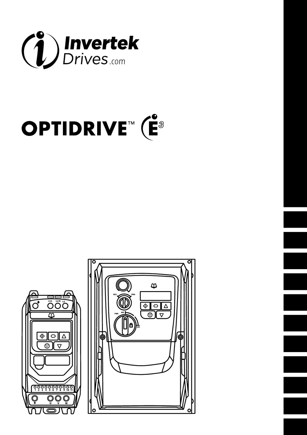
Visual guide to basic connection and operation for IP20/IP66 drives.
General guidelines for mounting the Optidrive safely and effectively.
Dimensions and mounting instructions for IP20 drives.
Best practices for mounting IP20 drives within enclosures for optimal cooling.
Visual representation of power and control wiring for different drive types.
Essential information on grounding procedures and safety.
Details on connecting the main power supply to the drive.
Guidance on connecting the motor to the Optidrive.
Detailed mapping of control terminals to signals and functions.
Guidelines for installing the drive to meet EMC standards.
Explanation of the keypad buttons and their functions.
Step-by-step process for modifying drive parameters.
Explains basic drive parameters for setup and control.
Selects how the drive receives control commands (keypad, terminal, fieldbus).
Selects the motor control method (V/f, Vector, etc.).
Introduces macro approach for input configuration and key parameters.
Macro configurations for terminal control mode.
Macro configurations for keypad control mode.
Macro configurations for fieldbus control modes.
Illustrative diagrams for various input signal connections.
Table of Modbus registers for controlling and monitoring the drive.
Tables detailing drive ratings, cable sizes, and fuse recommendations.
List of fault codes, their descriptions, and suggested remedies.
| Output Voltage | 0-Input Voltage |
|---|---|
| Enclosure Rating | IP20 |
| Control Method | Sensorless Vector Control |
| Protection Features | Overcurrent, Overvoltage, Undervoltage, Overtemperature, Short Circuit |
| Communication Options | Modbus RTU |
| Operating Temperature | -10°C to 50°C (14°F to 122°F) |
| Humidity | 95% RH (non-condensing) |
| Cooling Method | Fan Cooled |
| Input Voltage | 200-240V AC (1-phase), 380-480V AC (3-phase) |

