Optidrive ODE-2 User Guide Revision 3.30
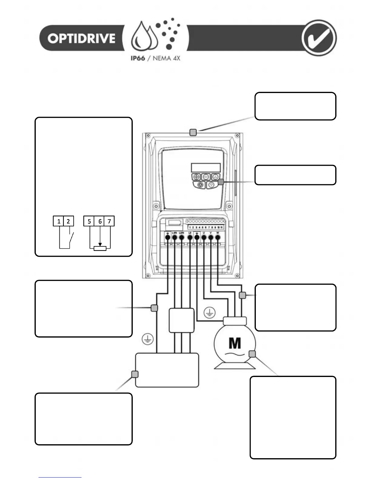
Mechanical Mounting
- Information can be found
on page 10
Keypad operation can be found
on page 16
Motor Cable Information
- Check the rating
information on page 26 for
sizing information
- For EMC compliance, use a
shielded type cable
Motor Connections
- Check for Star or Delta
connection according to the
motor nameplate and voltage
rating (See page 13)
Motor Nameplate Details
- Enter the motor rated voltage
in P-07
- Enter the motor rated current
in P-08
- Enter the motor rated
frequency in P-09
Supply Voltage
- 110 – 115, 200 – 240, 400 – 480
VAC + / - 10%
- 1 or 3 Phase
Check the drive rating information on
page 26
Fuses or MCB
- Fuse Ratings given on page 26
- Recommended cable sizes shown
on page 26
Always follow local and national codes
of practice
Control Terminals
Based on the factory default (out of box)
settings
- Connect a Start / Stop switch
between terminals 1 & 2
- Close the switch to Start (Enable)
the drive
- Open the switch to Stop (Disable)
the drive
- Connect a potentiometer (5kΩ
minimum) between terminals 5, 6
and 7 as shown below to vary the
speed from minimum (0Hz) to
maximum (50 / 60 Hz)
Earth L N
L1 L2 L3
AC Supply Voltage
(50 / 60 Hz)