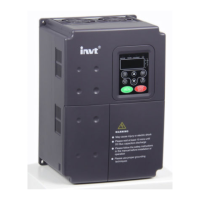
What does external fault mean on INVT CHE100-2R2G-S2?
- Ttim32Sep 8, 2025
If the INVT DC Drive displays an external fault, it means the external fault input terminal is active. Inspect the external equipment.

What does external fault mean on INVT CHE100-2R2G-S2?
If the INVT DC Drive displays an external fault, it means the external fault input terminal is active. Inspect the external equipment.
What causes current detection fault in INVT CHE100-2R2G-S2?
If the INVT DC Drive displays a current detection fault, it could be due to loose wires or connectors on the control board, a damaged Hall sensor, or an abnormal amplifying circuit. Check the wiring.
How to fix autotuning fault in INVT CHE100-2R2G-S2 DC Drives?
If the INVT DC Drive displays an autotuning fault, it could be due to improper settings of the motor's rated parameters or the autotuning process timing out. Set the rated parameters according to the motor nameplate and check the motor’s wiring.
What does EEPROM fault mean in INVT DC Drives?
If the INVT DC Drive displays an EEPROM fault, it indicates a read/write fault of control parameters. Press STOP/RESET to reset.
What causes PID feedback fault in INVT DC Drives?
If the INVT DC Drive displays a PID feedback fault, it could be due to a disconnected PID feedback or a disappearing PID feedback source. Inspect the PID feedback signal wire and the PID feedback source.
How to troubleshoot brake unit fault in INVT CHE100-2R2G-S2?
If the INVT DC Drive shows a brake unit fault, it could be due to braking circuit failure, a damaged brake tube, or too low resistance of the externally connected braking resistor. Inspect the braking unit and replace the braking tube if necessary. Increase the braking resistance.
| Model | CHE100-2R2G-S2 |
|---|---|
| Power | 2.2 kW |
| Frequency Range | 0-400Hz |
| Control Method | V/F control |
| Protection Level | IP20 |
| Communication Interface | RS485 |
| Ambient Temperature | -10°C to +40°C |
| Storage Temperature | -20°C to +60°C |
| Protection Features | Overcurrent, Overvoltage, Undervoltage, Short circuit |
| Humidity | 5-95% RH, non-condensing |
| Altitude | Up to 1000m |
Specifies the necessary environmental conditions for proper inverter operation.
Details the required clearances for inverter installation and ventilation.
Illustrates the connection of external devices to the inverter's power circuit.
Details the main and control circuit terminal layouts for different inverter sizes.
Presents a general schematic showing inverter wiring with peripheral components.
Provides instructions for connecting the main power circuits of the inverter.
Details the wiring procedures for the inverter's control circuits.
Explains the layout and functions of the inverter's control keypad.
Explains vector control parameters for advanced motor speed and torque regulation.
Manages motor overload, over-voltage, and current limiting protection settings.
Lists common fault codes, their reasons, and recommended solutions.
Provides solutions for common operational malfunctions like no display or motor not moving.
Outlines routine inspection tasks for the inverter, motor, and operation status.
Lists parameters for configuring motor characteristics like power, voltage, and current.
Lists protection parameters like motor overload and over-voltage stall.
Describes communication interfaces (RS485) and Modbus communication modes.
Details Modbus RTU and ASCII frame formats and protocol functions.


 Loading...