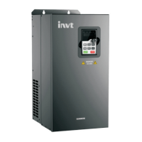
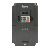
CHV180 series frequency inverter special for elevator Content
.1.
Content
Content ................................................................................................................................. 1
Safety precautions .............................................................................................................. 3
1. General ............................................................................................................................. 4
1.1 General technical specifications ........................................................................... 4
1.2 Description of name plate ..................................................................................... 5
1.3 Selection guide...................................................................................................... 5
1.4 Parts description ................................................................................................... 6
1.5 Description of extension card ............................................................................... 7
2. Unpacking inspection .................................................................................................... 9
3. Disassembly and installation ...................................................................................... 10
3.1 Environmental requirement................................................................................. 11
4. Wiring ............................................................................................................................. 12
4.1 Connections of peripheral devices ..................................................................... 13
4.2 Terminal configuration ......................................................................................... 13
4.3 Typical wiring diagram ........................................................................................ 15
4.4 Wiring the main circuits ....................................................................................... 15
4.5 Wiring control circuit terminals............................................................................ 18
4.6 Installation guidline to EMC compliance ............................................................ 20
5. Operation..................................................................................................................... 24
5.1 Operating keypad description ............................................................................. 24
5.2 Operation process ............................................................................................... 26
5.3 Running state ...................................................................................................... 28
6. Detailed function description ................................................................................... 30
6.1 P0 Group--Basic function.................................................................................... 30
6.2 P1 Group--Speed curve ...................................................................................... 36
6.3 P2 Group--Motor parameters ............................................................................. 43
6.4 P3 Group--Vector control .................................................................................... 45
6.5 P4 Group -- Encoder parameter ......................................................................... 48
6.6 P5 Group--Input terminals .................................................................................. 50
6.7 P6 Group -- Output terminals ............................................................................. 55
6.8 P7 Group –Human-Machine interface................................................................ 61
6.9 P8 Group --Enhanced function ........................................................................... 66
6.10 P9 Group -- Protection parameters .................................................................. 71
6.11 PA Group --Serial communication .................................................................... 73
6.12 Pb Group – Display monitor ............................................................................. 76
6.13 PC Group –Load starting parameters .............................................................. 77

 Loading...
