unit
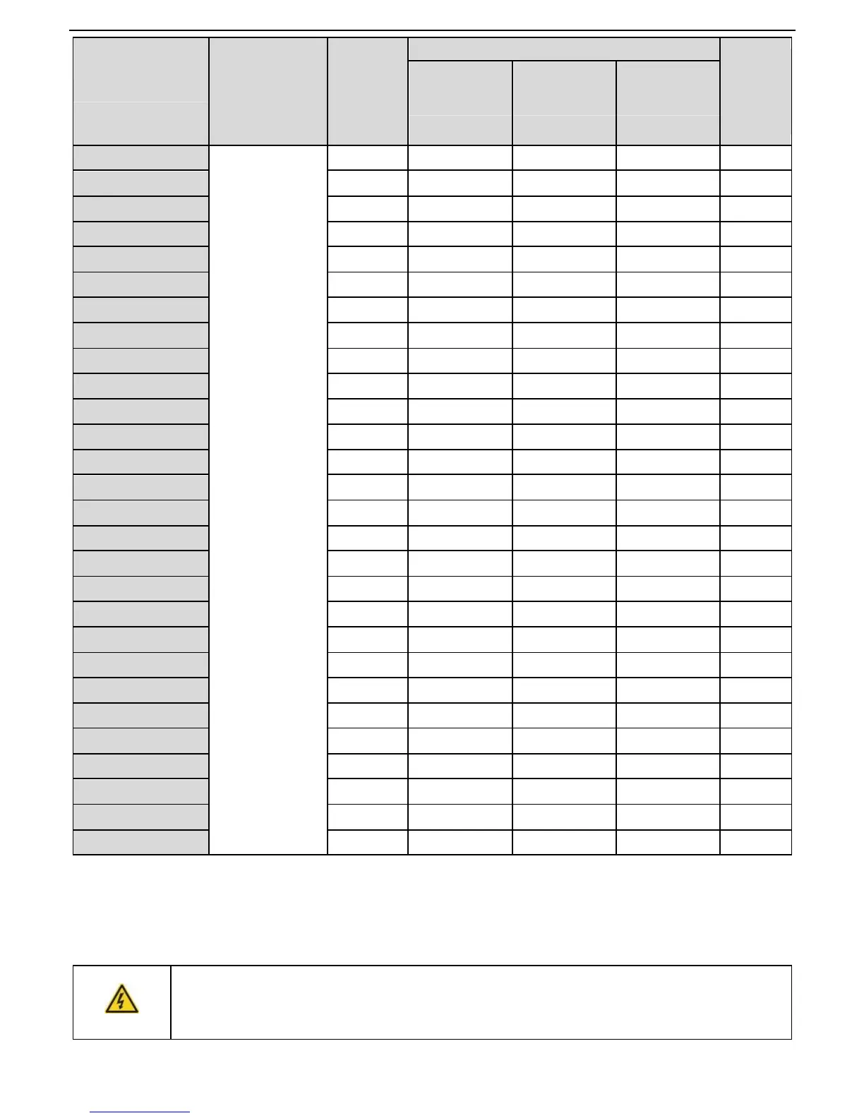
361 0.06 0.30 0.48 42
GD20-0R7G-S2 192 0.11 0.56 0.90 42
GD20-1R5G-S2 96 0.23 1.10 1.80 30
GD20-2R2G-S2 65 0.33 1.70 2.64 21
GD20-0R4G-2 361 0.06 0.3 0.48 131
GD20-0R7G-2 192 0.11 0.56 0.9 93
GD20-1R5G-2 96 0.23 1.1 1.8 44
GD20-2R2G-2 65 0.33 1.7 2.64 44
GD20-004G-2 36 0.6 3 4.8 33
GD20-5R5G-2 26 0.75 4.13 6.6 25
GD20-7R5G-2 19 1.13 5.63 9 13
GD20-0R7G-4 653 0.11 0.56 0.90 240
GD20-1R5G-4 326 0.23 1.13 1.80 170
GD20-2R2G-4 222 0.33 1.65 2.64 130
GD20-004G-4 122 0.6 3 4.8 80
GD20-5R5G-4 89.1 0.75 4.13 6.6 60
GD20-7R5G-4 65.3 1.13 5.63 9 47
GD20-011G-4 44.5 1.65 8.25 13.2 31
GD20-015G-4 32.0 2.25 11.3 18 23
GD20-018G-4 27 3 14 22 19
GD20-022G-4 22 3 17 26 17
GD20-030G-4 17 5 23 36 17
GD20-037G-4 13 6 28 44 11.7
GD20-045G-4-B
4.5 17 83 132 4.4
Note:
Select the resistor and power of the braking unit according to the data our company provided.
The braking resistor may increase the braking torque of the inverter. The resistor power in the above table is
designed on 100% braking torque and 10% braking usage ratio. If the users need more braking torque, the
braking resistor can decrease properly and the power needs to be magnified.
Never use a brake resistor with a resistance below the minimum value specified
for the particular drive. The drive and the internal chopper are not able to handle
the overcurrent caused by the low resistance.
 Loading...