Goodrive20-EU series VFD Communication protocol
138
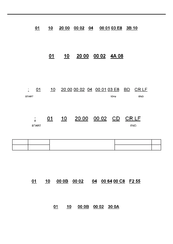
The command sent to the VFD:
VFD
address
Continuous
writing
command
Parameters
address
CRC check
Byte
number
Forward
running
10Hz
Data
number
If the operation succeeds, the response message is as follows:
Continuous
writing
command
VFD
address
Parameters
address
CRC check
Data
number
ASCII mode:
The command sent to the VFD:
Continuous
writing
command
Parameters
address
Data
number
Byte
number
Forward
running
VFD
address
LRC
check
If the operation succeeds, the response message is as follows:
Continuous
writing
command
Parameters
address
Data
number
VFD
address
LRC
check
Example 2: set the ACC time of 01H VFD as 10s and the DEC time as 20s
Setting range of P00.11 and P00.12:
0.0 – 3600.0s
The corresponding address of P00.11 is 000B, the ACC time of 10s corresponds to 0064H,
and the DEC time of 20s corresponds to 00C8H.
RTU mode:
The command sent to the VFD:
Continuous
writing
command
VFD
address
Parameters
address
CRC check
Byte
number
10s 20sData
number
If the operation succeeds, the response message is as follows:
Continuous
writing
command
VFD
address
Parameters
address
CRC check
Data
number
ASCII mode:

 Loading...


