Goodrive20-EU series VFD Installation guide
18
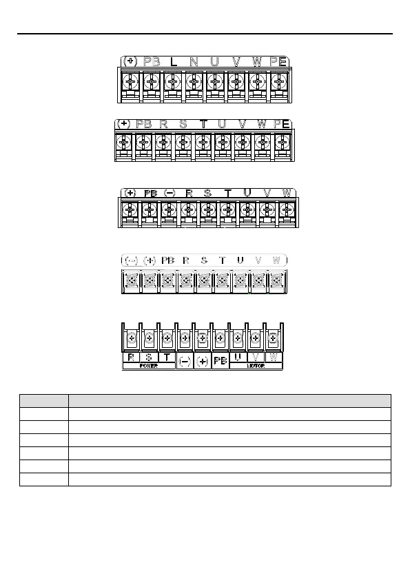
3.2.2 Terminals figure of main circuit
Figure 3-4 1PH terminals of main circuit (single phase)
Figure 3-5 3PH terminals of main circuit (230V, ≤0.75kW, and 400V, ≤2.2kW)
Figure 3-6 3PH terminals of main circuit (230V, ≤1.5kW, and 400V, 4-22kW)
Figure 3-7 3PH terminals of main circuit (30-37kW)
Figure 3-8 3PH terminals of main circuit (45-110kW)
Single phase AC input terminals, connected to the power supply.
Three phase AC input terminals, connected to the power supply.
External dynamic brake resistor terminal
Input terminal of the DBU or DC bus
Three phase AC input terminals which are generally connected to motor.
Protective grounding terminal
Note:
Do not use asymmetrically motor cables. If there is a symmetrically grounding conductor
in the motor cable in addition to the conductive shield, connect the grounding conductor

 Loading...


