Goodrive20-EU series VFD Installation guide
22
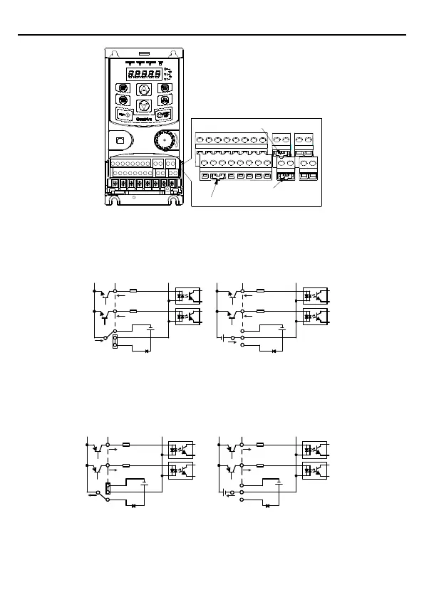
U-shaped tag between +24V and H1
U-shaped tag between COM and PW
U-shaped tag between +24V and H2
Figure 3-12 U-shaped contact tag
If the signal is from NPN transistor, set the U-shaped contact tag between +24V and PW as
below according to the used power supply.
S1
S2
COM
PW
+ 24V
COM
+24V
内部电源(模式)NPN
S1
S2
COM
PW
+ 24V
COM
+ 24V
外部电源(模式)NPN
+ 24V
Internal power supply
External power supply
Figure 3-13 NPN modes
If the signal is from PNP transistor, set the U-shaped contact tag as below according to the
used power supply.
S1
S2
COM
PW
+ 24V
COM
+24V
外部电源(模式)PNP
S1
S2
COM
PW
+24V
COM
+24V
内部电源(模式)PNP
Internal power supply External power supply
Figure 3-14 PNP modes

 Loading...


