Goodrive300-01A series VFD for air compressor Wiring instruction
-17-
Figure 3-17 485 communication wiring diagram (isolation mode) for 75kW and above
Note: When users choose to use the controller, for 75kW and above models, J10 cap can be
adjusted and above wiring mode can be adopted to enhance anti-interference performance.
●
●
●
COM
+24V
PW
COM
+24V
•
•
S1
S2
•
J9
COM
+24V
PW
COM
+24V
•
•
S1
S2
•
●
●
●
+24V
J9
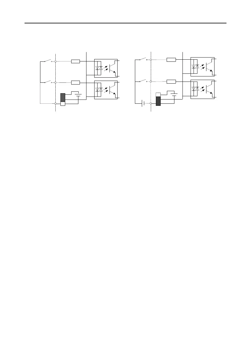
Figure 3-18 Internal power (NPN mode) Figure 3-19 External power (PNP mode)
When the digital input uses internal +24V, set J9 according to Figure 3-18, and short +24V to PW.
When digital input uses external +24V, set J9 according to Figure 3-19, and short COM to PW.

 Loading...


