Goodrive300-01A series VFD for air compressor Wiring instruction
-16-
2. Error±3%, 25°C
3. Input impedance: 50Ω
Note: See Appendix C for model
selection of current transformer.
B-phase current input of
the fan
C-phase current input of
the fan
P1-Analog signal
selection terminal
I corresponds to current signal, V
corresponds to voltage signal, and the
default is current input signal.
P2-Analog signal
selection terminal
I corresponds to current signal, V
corresponds to voltage signal, and the
default is current input signal.
AO1 analog output signal
selection terminal
I corresponds to current signal, V
corresponds to voltage signal, and the
default is voltage output signal.
Connection terminal of
485 communication
terminal resistor
ON corresponds to terminal resistor. ON
is not connected to terminal resistor by
default.
Short-connect terminal
between PE and GND
No short connection by default
Internal/external power
selection terminal
PW is connected to +24V by default. See
details in fig 3.19 and fig 3.20.
PE/CGND selection
terminal
For products below 75kW, 485
communication adopts non-isolation
mode, and CN7-10 is short connected to
PE by default.
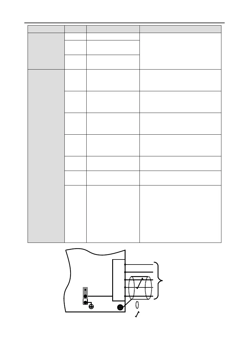
For 75kW and above products, 485
communication adopts isolation mode,
and CN7-10 is short connected to CGND
by default, as shown in fig 3.18.
CGND
J10
to controller
PE
CN7-10
GND
+24V
485-
485+
/PE
CGND
--twisted pair
--shielded cable
PE
H9

 Loading...


