EasyManuals Logo

INVT Goodrive300 Series User Manual

INVT Goodrive300 Series
289 pages
To Next Page IconTo Next Page
To Previous Page IconTo Previous Page
Page #20 background imageLoading...
Page #20 background image
Goodrive300 Series VFD Product overview
15
4
6
7
1
2
3
14
13
9
10
11
12
8
5
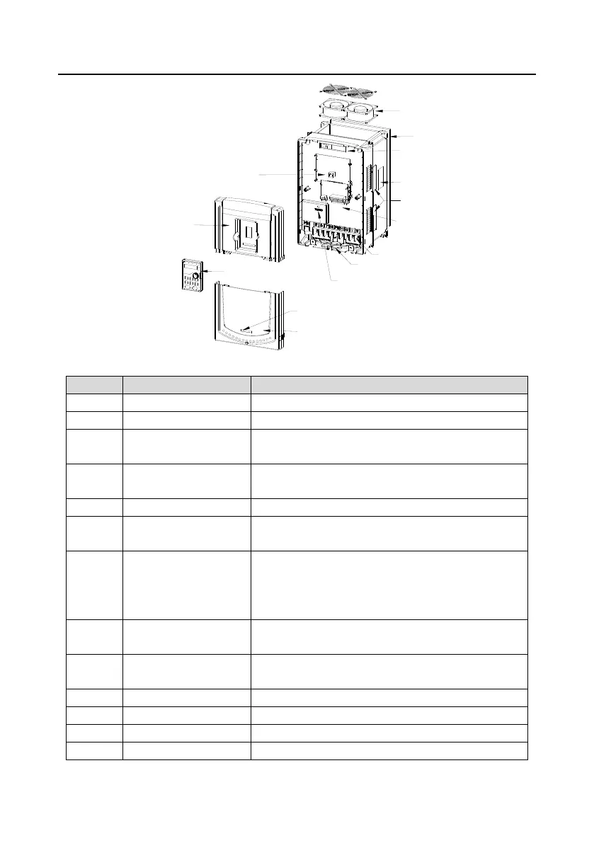
Figure 3-8 Product structure
No.
Name
Description
1
Keypad port
Connect the keypad.
2
Upper cover
Protect the internal parts and components.
3
Keypad
See Chapter 5 "Keypad operation procedure" for detailed
information.
4
Cooling fan
See Chapter 9 "Maintenance and hardware fault
diagnostics" for detailed information.
5
Wiring port
Connect to the control board and the drive board.
6
Name plate
See Chapter 3 "Product overview" for detailed
information.
7
Side cover
Optional. The side cover will increase the protective
degree of the VFD, however, the internal temperature of
the VFD will also increase, so it is necessary to derate
the VFD at the same time.
8
Control terminals
See Chapter 4 "Installation guide" for detailed
information.
9
Main circuit terminals
See Chapter 4 "Installation guide" for detailed
information.
10
Main circuit cable port
Fix the main circuit cable.
11
POWER light
Power indicator.
12
Simple name plate
See section 3.5 "Model code" for detailed information.
13
Lower cover
Protect the internal parts and components.

Table of Contents

Questions and Answers:

Question and Answer IconNeed help?

Do you have a question about the INVT Goodrive300 Series and is the answer not in the manual?

INVT Goodrive300 Series Specifications

General IconGeneral
BrandINVT
ModelGoodrive300 Series
CategoryDC Drives
LanguageEnglish

Related product manuals