-11-
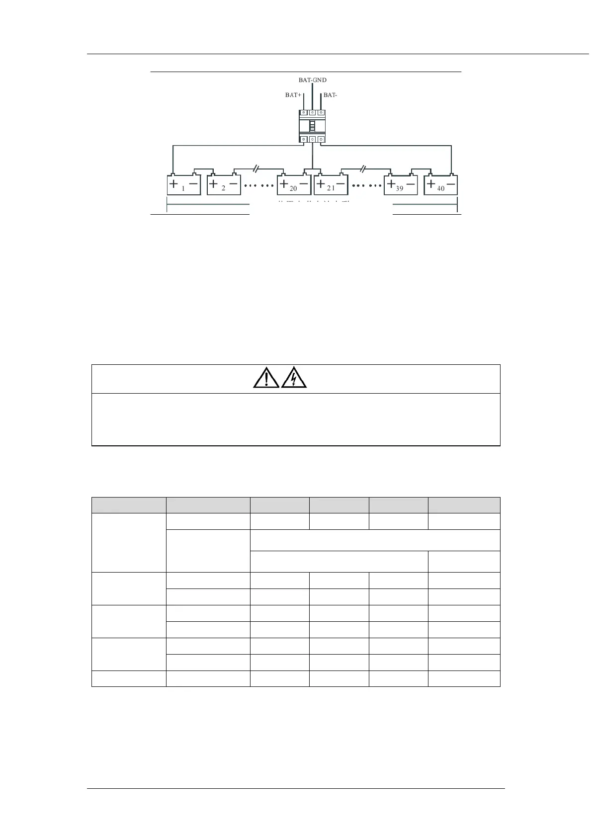
Fig 2-4 Diagram of batteries connected in series
2.4.3 UPS Output
A main output switch has been installed in UPS; the user shall install the overcurrent protective
device on the bypass of each output of the external distribution cabinet.
2.5 Power Cables
Design the cables according to the descriptions in this section and local regulatory wiring standards,
and the environmental conditions should be taken into consideration. Refer to IEC60950-1 table 3B.
Warning
Prior to cabling the UPS, confirm the status and positions of the switches of the UPS rectifier input
power supply / bypass power supply and mains power distribution board.
Ensure that these switches are opened and attached with WARNING label so as to prevent
unauthorized operation to these switches.
2.5.1 Maximum stable state current and configuration of cable system
Table 2-1 Maximum stable state current and configuration of cable system
System Name HT 33010 HT 33015 HT 33020 HT 33030
Capacity System capacity 10KVA 15KVA 20KVA 30KVA
Cabinet
dimension mm
W*D*H
540*690*1100 (with built-in battery)
280*730*668 (without built-in battery) 320* 781* 788
Main Input Rated current A 15 22.5 30 45
Cable mm2 4 6 10 10
Output Rated current A 15 22.5 30 45
Cable mm2 4 6 10 10
Battery Rated current A 18 26.5 36 53
Cable mm2 6 10 10 16
PE Cable mm2 10 10 16 25
Forty batteries in series connection in total