iMars grid-tied solar inverters Installation
29
4.4.1 Connection of solar modules
5
1
1
2
2
2
2
3
3
44
5
Figure 4.15 Connection between DC connector and solar modules
Connection steps:
(1) Lighting, short-circuit and other protection measures which meet the local electrical safety
laws and regulations are needed before the AC connection;
allowed to connect.
(2) Connect the output cables of solar modules to the DC connector as figure 4.15 shows.
Loose the nut of connector and remove the isolation layer of the DC cable for about 15mm.
Insert it into the connector and press until heart the lock sound. Finally fasten the nut to a
torque of 2.5-3 Nm. The wiring of negative pole is the same as that of the positive pole.
Ensure the poles of solar modules are well connected with the connectors;
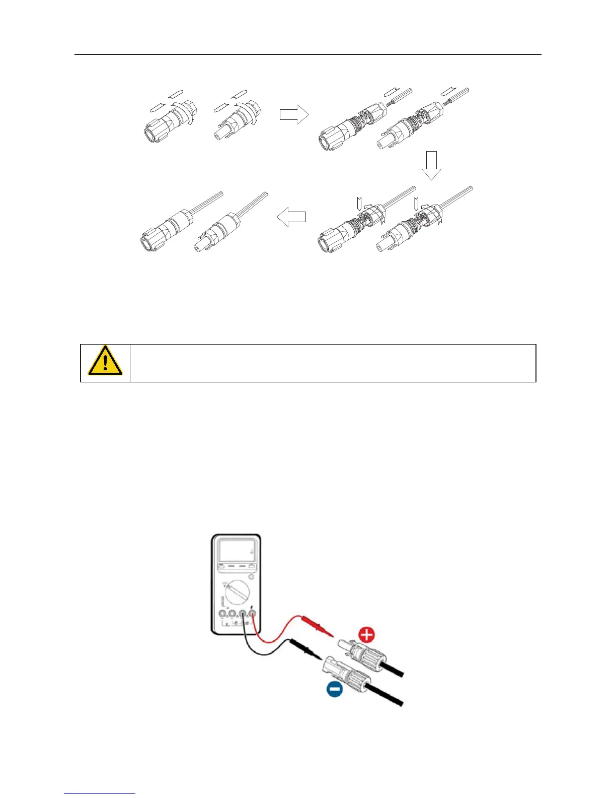
(3) After the DC connector is connected, use a multimeter to measure the voltage of the DC
input string, verify the polarity of the DC input cable, and ensure that the voltage of each
string is within the allowable range of the inverter, as shown in Figure 4.16.
Figure 4.16 DC input voltage measuring