iMars grid-tied solar inverters Monitoring communication
58
Please download the connection instruction, operation manual and commissioning tools on
website www.invt-solar.com.
Note: the optional accessories are not standard-configured.
7.3 RS485-DRM ports
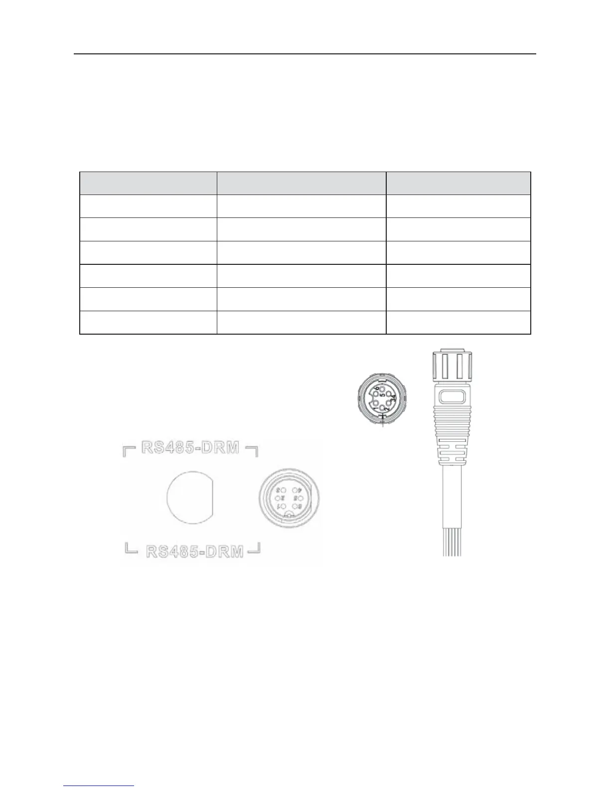
Table 7-3 RS485-DRM Pins on inverter instruction
Pin on inverter Colour Definition
1 Red RefGen
2 Yellow Com/DRM0
3 White DRM1/5
4 Black DRM2/6
5 Green DRM3/7
6 Blue DRM4/8
Figure 7.5 RS485-DRM pin on inverter Figure 7.6 Connection cable
RS485-DRM connection steps:
(1) Weld communication cables to the RS485-DRM terminals of the inverter as figure 7.6 shows;
Ensure the cable corresponds to the pin as table 7-3 shows and the welding is tight enough.
According to Table 7-3, connect the communication connector pinout and the user's device, make
sure the connection is correct.