3.2.3 Structures
ISC-B01
ISC-02
ISC-03
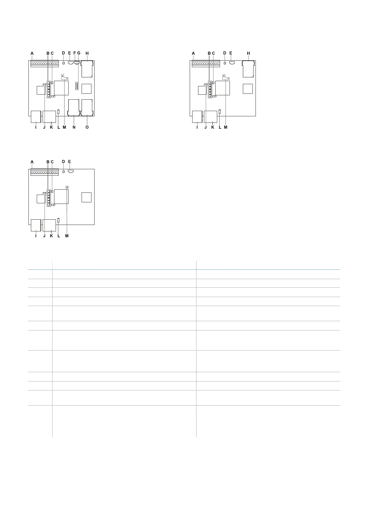
Part Description Control unit
A I/O terminal block ISC-B01, ISC-02, ISC-03
B System status LEDs ISC-B01, ISC-02, ISC-03
C Network parameter reset button ISC-B01, ISC-02, ISC-03
D Reserved for internal use. Output reset button ISC-B01, ISC-02, ISC-03
E Micro-USB port for connecting the PC and
communicating with the Inxpect Safety application
ISC-B01, ISC-02, ISC-03
F Micro-USB port (reserved) ISC-B01
G Fieldbus status LEDs
See "Fieldbus status LEDs" on the next page
ISC-B01
H Ethernet port with LEDs for connecting the PC,
communicating with the Inxpect Safety
application, and for Modbus communication
ISC-B01, ISC-02
I Power supply terminal block ISC-B01, ISC-02, ISC-03
J Power supply LEDs (steady green) ISC-B01, ISC-02, ISC-03
K CAN bus terminal block for connecting the first
sensor
ISC-B01, ISC-02, ISC-03
L DIP switch to turn on/off the bus termination
resistance:
l On (top position, default) =resistance included
l Off (bottom position)= resistance excluded
ISC-B01, ISC-02, ISC-03
3. Get to know SBV System Series
SBV System Series| Instruction manual v1.2 DEC 2021|SAF-UM-SBVBus-en-v1.2|© 2021 Inxpect SpA
15