640 & 650 Series 878893 Connectors, Indicators, and Cables 3-1
Connectors, Indicators, and Cables 3
Front Panel Connectors and Indicators …… 3-1
The Rear Pannel …… 3-2
Unit Underside …… 3-3
Accessories …… 3-4
Front Panel Connectors and Indicators
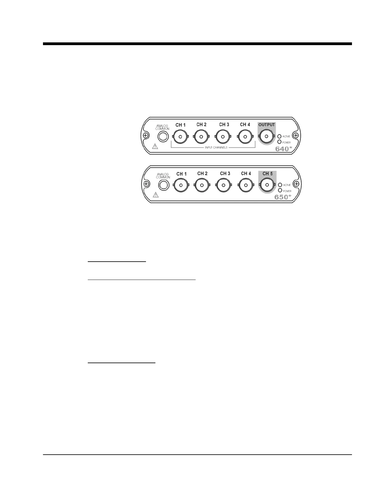
640 and 650 Front Panels
*
The actual model number includes an “e” or “u” to indicate Ethernet or USB version.
The 640 and 650 Front Panels include the following connectors and LED indicators.
ANALOG COMMON
: Common analog ground.
ANALOG SIGNAL INPUT CHANNELS
: These BNC connectors are used for voltage input. The 640
models have 4 input channels. The 650 models have 5 input channels.
The BNC center-conductor is the signal HI and the BNC shell is the signal LO. Each BNC shell is
connected to the chassis ground through its own channel-dedicated 1 kΩ resistor. Consequently, the shell
is not meant to be driven with respect to earth ground more than ±10V.
An additional consideration pertains to input transducer setup. If the transducer case is effectively earth
grounded through its connection to a device under test, there exists the possibility for added measurement
noise due to the ground loop that is created. The pseudo-differential input rejects much of this noise.
Electrically isolating the transducer from the test device minimizes noise.
OUTPUT (640 units only)
: The 640 units include a programmable voltage source that can be set in
discrete amplitudes (see specifications). The output waveform parameters are controlled by software and
can be sine, swept-sine, random, burst, or arbitrary. The output can be used as a test source for the input
channels or as excitation for other system elements, such as the amplifier for a shaker table. Detailed
information on the excitation source and its operation can be found in the applicable eZ software
documentation, e.g., the eZ-Analyst User’s Manual.
NOTE: The output value is not guaranteed unless the Power LED has lit.