5-6 Configuring USB Models 640u & 650u 889793 640 & 650 Series
Connecting Data Acquisition Signal Lines
Prior to making signal connections review the Specifications chapter to ensure that signal inputs do not
exceed the specified limits.
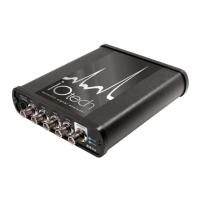
The 640u
4 analog channel inputs (CH1 through CH4) via front panel BNC connectors.
1 analog output via the fifth front panel BNC connector.
8 digital I/O lines via rear panel DB9 connector, as discussed in Chapter 3,
Connectors, Indicators, and Cables.
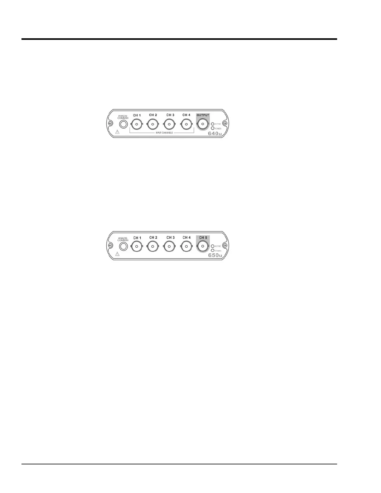
The 650u
5 analog channel inputs (CH1 through CH5) via front panel BNC connectors.
8 digital I/O lines via rear panel DB9 connector, as discussed in Chapter 3,
Connectors, Indicators, and Cables.