Specifications are subject to change without notice.
11-4 Specifications 927791 IOtech 640 and 650
Digital I/O Lines Note: To make use of Digital I/O, eZ-TOMAS or eZ-NDT software must be
running in the host PC.
Channels: 8 Digital I/O, programmable as inputs or
outputs on a line by line basis
Ports: 1 x 8-bit, Each bit is programmable as input or
output
Power-up mode: Inputs pulled low
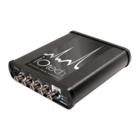
Connector: DB-9 female (figure)
Input Scanning Modes: 2 programmable scanning modes Asynchronous, under program control at any
time relative to Analog scanning; Synchronous with Analog scanning
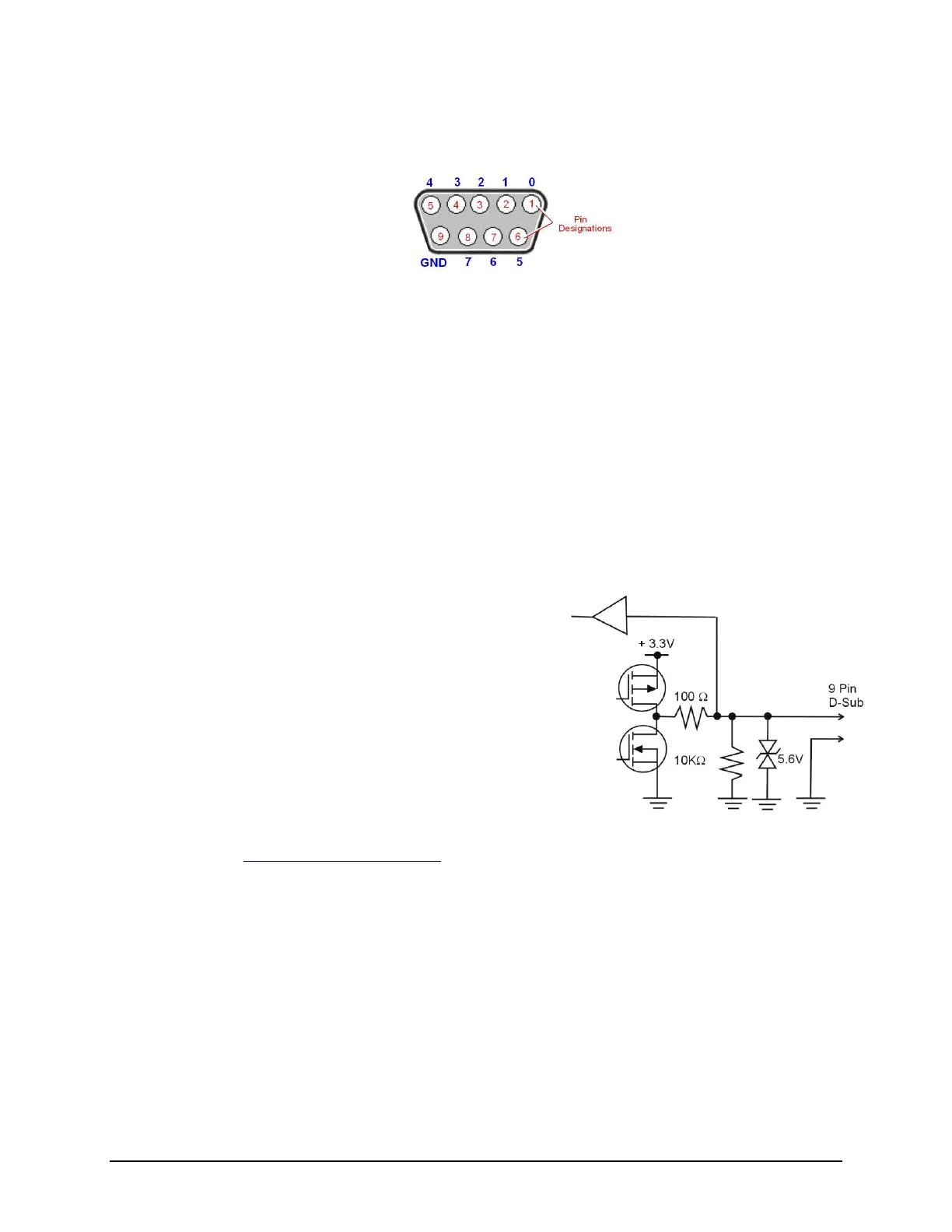
Input Protection: ±5.6V
Input Levels:
Low: 0 to +0.8V
High: +2.0V to +5.0V
Input pull-down resistor: 10kΩ
Output voltage range: 0 to +3.3V, may be pulled up to +5V
Output resistance: 100Ω
Output Levels:
Low: < 0.8V
High: >3.0V with no load
Sampling:
105,468Hz, maximum
Note: A Digital I/O example is located in section 11.b.
See Figure XXI. Digital I/O I-V Curve
Output timing: Outputs are always written asynchronously.
DB9 – As viewed from the rear panel. Outer numbers are
digital channels. Inner numbers are pin designations.