Technisch manual IPC MicroTimer IPC Systems B.V.
Technisch manual IPC MicroTimer Pagina 13
Versie 1.3
Ontwikkelingsspecificaties, wijzigingen voorbehouden Datum 14-03-‘02
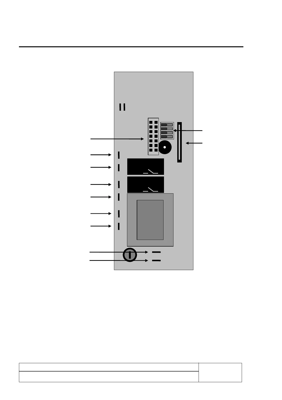
Wiring diagram: 4
Connections of the signals at the rear-side of the circuit-board:
*Dip-switch working: 1 = On Stop button present
1 = Off Stop button not present
2 = On Timer button present
2 = Off Timer button not present
3 = On Start / Pause present
3 = Off Start / Pause not present
4 = On Modification of the settings is possible
4 = Off Modification of the settings is not possible
Relais 1 max.
6,3A
Relais 2 max.
6,3A
Power supply
230V AC
Connection output 1
Connection output 2
Power supply
24V AC/DC
Connection “long
distance” pcb
Dipswitchen *
Connection
keypanel