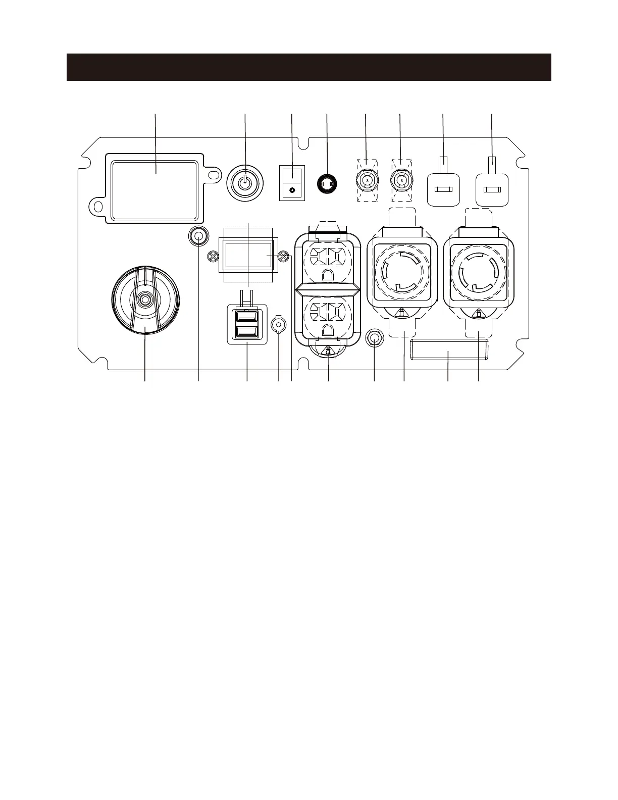
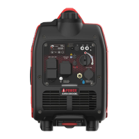
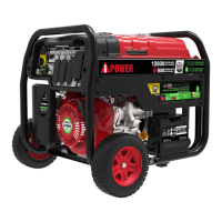
CONTROL PANEL FEATURES
Page 10
NOTE: Total power drawn from all outlets must not exceed the nameplate rating.
1. LED Data Center: See LED DATA CENTER section.
2. Push-Button START/STOP: Push once to automati-
cally start the engine. Push again to stop the engine.
3. Battery Switch: Restore the battery power to the
control module. you must turn the switch to ON position
before start the generator.
4. Romote Set Button: To pair the new remote control
fob.
5. Circuit Breaker(AC): Protects the generator against
electrical overloads.
6. Parallel Operation Outlets: These outlets are used
for connecting two AIPOWER inverter generators for
parallel operation. Do not connect or disconnect parallel
cables while the generator is running to avoid damage.
7. 120/240V AC, 30A Twist Lock, Single Phase,60Hz
Outlet (NEMA L14-30R): supply either 120 Volt or 240
Volt output up to 30 amps.
8. LED Light
9. 120V AC, 30A Twist Lock Outlet, Single pPhase,60
Hz Outlet (NEMA L5-30R): This receptacle can
provide120 volt output up to 30 amps.
10. Grounding Terminal: To ground the generator.
11. 120V AC, 20A Duplex, Single Phase, 60Hz Outlets
(5-20R): Each outlet is capable of carrying a maximum
of 20 amps on a single outlet or a ombination of both
outlets.
12. Voltage Selector Switch: To select 120 Volt or 240
Volt. Turn generator off before switching voltages.
15. CO (Carbon Monoxide) WATCH-GUARD Indicator
Light (Red for Shut off and Yellow for Service): The
CO(Carbon Monoxide) WATCH-GUARD monitors for the
accumulation of poisonous CO gas around the genera
-
tor produced by engine exhaust when the generator is
running. If the CO WATCH-GUARD detects increasing
levels of CO gas, it automatically shuts off the engine.
See CO WATCH-GUARD section for more information.
16. Starting Dial Switch: Used to start and stop the
generator.
14. 5V DC 2x2.4A: This outlet can supply 5 Volt up
to 2.4 amps.
1 2 3 4 5 5 6 6
791114 1316 15 12 10 8
13. 12V DC Battery Charger Inlet: Plug the battery
float charger to this inlet and 120V wall outlet to
charge the generator battery when the generator is
not running.