v
FIGURES
Figure Page
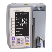
1-1 Front of Pump...................................................................................1-2
1-2 Pump Drive Door Open.......................................................................1-3
1-3 Back of Pump....................................................................................1-4
1-4 Model 1120 MRI Power Supply ............................................................1-5
1-5 Front of 3865 Remote Display/Charger.................................................1-6
1-6 Back of 3865 Remote Display/Charger..................................................1-7
1-7 Front Panel Control Keys ....................................................................1-8
1-8 Setup Display Screens......................................................................1-13
1-9 Running Screens .............................................................................1-15
1-10 Special Features Setup Menu ............................................................1-18
3-1 Free Flow Preventer...........................................................................3-1
3-2 Roller and Slide Clamps......................................................................3-1
3-3 IV Set Installation .............................................................................3-5
4-1 Primary Pump Setup Screen................................................................4-1
4-2 Dual Infusion Display.........................................................................4-5
4-3 Secondary Infusion Set-up and Programming Screen .............................4-7
4-4 Bolus Setup Displays..........................................................................4-9
4-5 Attaching Channel B “SideCar” ..........................................................4-11
4-6 Special Features Menu .....................................................................4-12
4-7 Dose Rate Calculation Menu..............................................................4-14
4-8 Primary Screen with Dose Rate Displayed ...........................................4-17
4-9 Alarm Volume Adjustment Screen......................................................4-21
4-10 KVO Rate Screen.............................................................................4-23
4-11 Set Comm Channel Displays .............................................................4-25
5-1 Alarm Display in User Message Area.....................................................5-2
6-1 Battery Installation............................................................................6-1
6-2 Battery Removal ...............................................................................6-2
6-3 Battery Test......................................................................................6-3
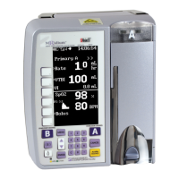
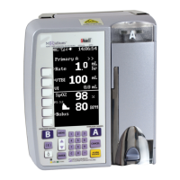
7-1 3860+ Display w/SpO2 ......................................................................7-4
7-2 Connecting the 1170 Fiberoptic Probe ..................................................7-9
7-3 Applying the 1170 SpO2 Sensor ........................................................7-10
7-4 Saturation Charting. ........................................................................7-19
Table Page
5-1 Alarm, Alert and User Prompt Messages ...............................................5-3
7-1 SpO
2
Alarm Limits.............................................................................7-8


 To Next Page