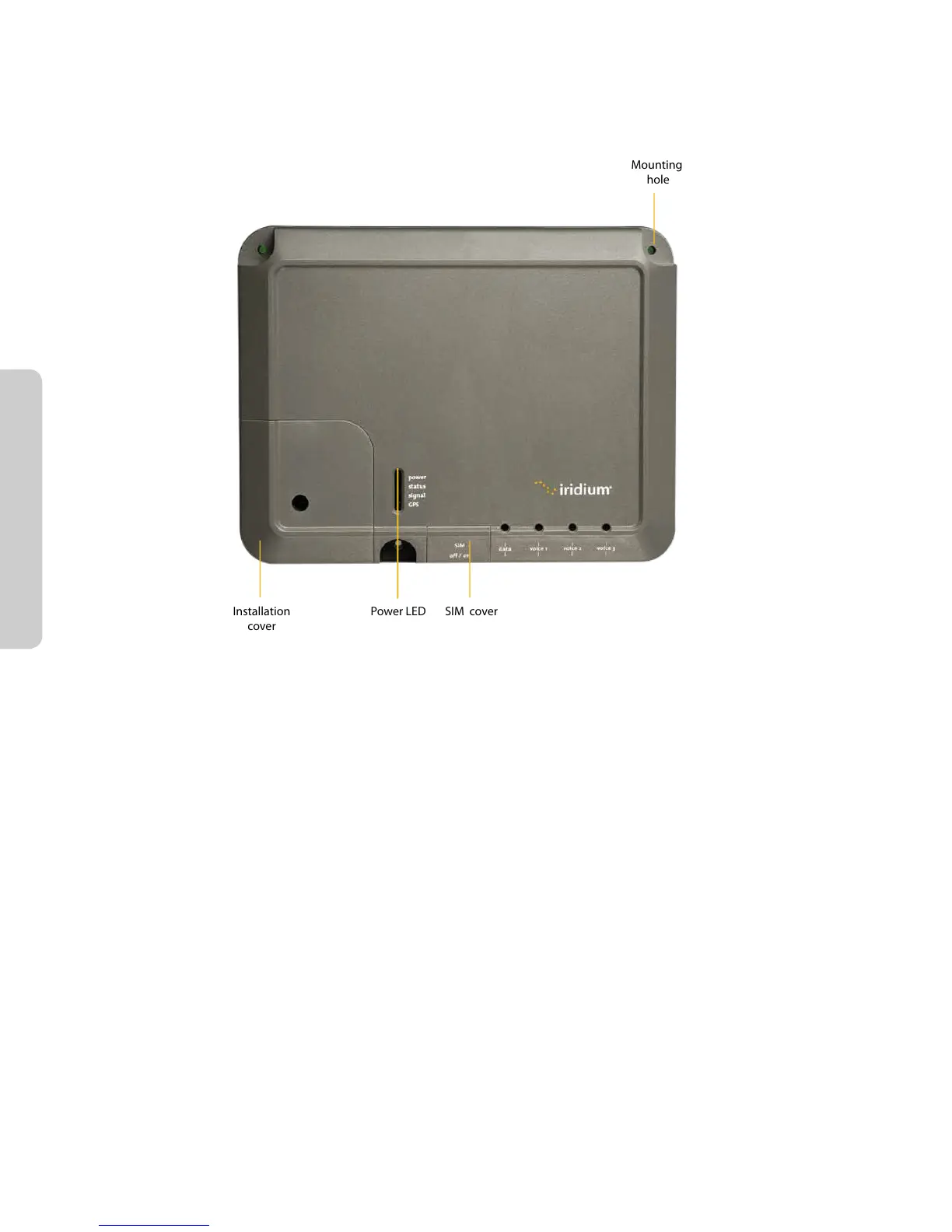
The data and handset connections are on the connector edge of the unit. There is one data connection and
three handset connections. The data connection is marked as “data” and the handset connections are identied
as “Voice 1”, “Voice 2” and “Voice 3”.
The handsets connected to the BDE must be POTS / RJ11 handsets. The data port MDI-X. If the Below Decks
Equipment (BDE) is to be connected to a down-stream port of an Ethernet hub or switch then the user will
need to use a cross-over cable. Again, the data port must be provisioned to connect to the Internet. The data
LED will illuminate green.
Note: According to standard Ethernet specications, the maximum length of the cable from the Ethernet
equipment to the Above Decks Equipment must not exceed 100m.