-SENSOR-HD-00-SWITCH-(IO)-00-(R)(1) Installation Manual | Released
Cabling diagram
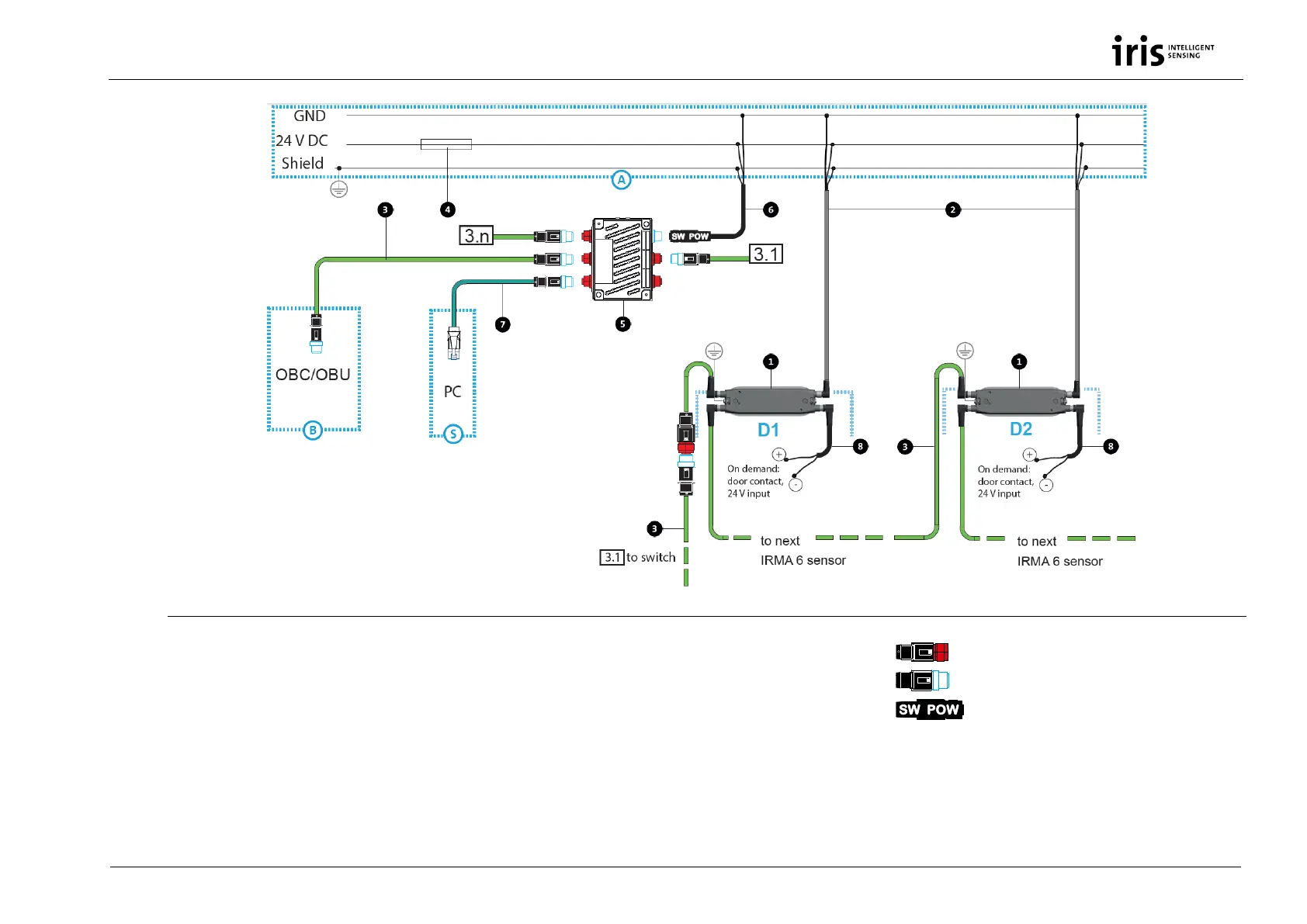
Fig. 3: Installation of IRMA 6 (Ethernet version) as door contact variant
1 IRMA 6 SWITCH variant (rear view on interface unit)
2 Power cable for IRMA 6 K-M12POW-B-oE-04-2m
3 M12 system cable, Ethernet K-M12CAT5-XX-xm
4 Fuse 5 A, quick-acting
5 Switch-M12-5Port-eCon
6 Power supply of switch, K-Switch-Power (= K2),
length 3 m or SAC-4P-5,0-28R/FS SCO RAIL (= K3)
7 Adapter cable for PC connection for service
purposes KQ-M12CAT5-RJ45-01-xm
8 Wires for setting door contacts (and opt. Door Clear)
A Distribution of the vehicle-provided power supply to each
door for the connection of IRMA 6 and switch. The distribution of
the vehicle-provided power supply to each door is not part of the
standard scope of delivery of iris-GmbH!
S PC connection for service purposes D1 to Dn
Doors with 1 IRMA 6
M12 connector (f), ETH type
M12 connector (m), ETH type
M12 connector (f), 4 poles, A coded (K-Switch-
Power)
B Connection to on-board computer/on-board
unit (On-Board Computer/Unit)