-SENSOR-HD-00-SWITCH-(IO)-00-(R)(1) Installation Manual | Released
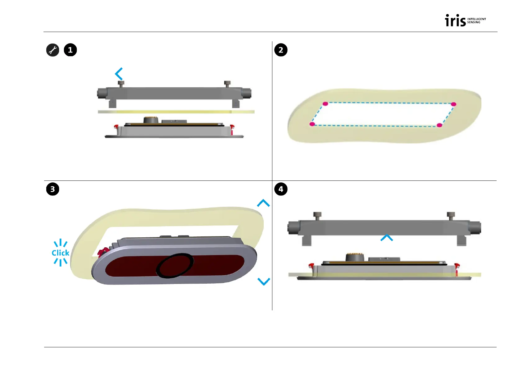
Choose position in door panel
Drill 4 holes and saw out template for IRMA 6
Travel direction
Drill 4 holes with drilling machine and saw ou the template with jig saw in the
door panel according to measures in attached drilling templates, see Drilling
templates, p. 27.
Put sensor unit in
Fit sensor unit into interface unit
Put the IRMA 6 sensor unit via the mounting hook into the drilled hole
in the door panel.
Fit in in the internal connector and the attaching form of the senor unit
into the interface unit which is above the door panel.
Interface unit
Sensor unit
1.7 -8 mm
Inside